About model templates
Updated: 09/19/2024
This page describes the functionality of model templates.
The model template is a convenient feature that allows you to apply elements such as parts, deformer structures, and parameter keyforms to a newly created model based on a completed Live2D model.
The model template makes it easy to transfer the features and movements of an existing model to a new model.
Please also see the following pages.
“How to apply model templates”
“Creating/exporting model templates”
Precautions
For versions prior to Cubism 5.1, the specifications of the model template function are different.
For more information, see “Model template function” in Cubism Editor 4.2.
Applying Model Templates
Model templates can also be applied to models that already contain deformers and parameters.
Select any ArtMesh and then apply the model template.
However, if no ArtMesh is selected, all ArtMeshes will be application targets.
Model Template Selection
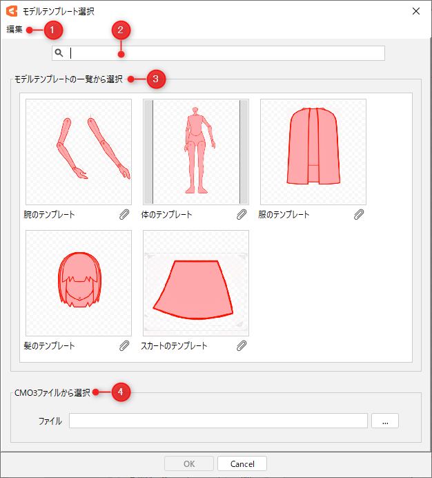
Select a model template in the [Model template selection] dialog box.
Select the [Modeling] menu -> [Model template] -> [Apply template] to display the [Model template selection] dialog box.
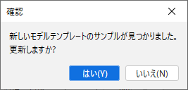
The first time you start the program, you will be able to download a sample model template, so select [Yes] in the confirmation dialog box.
| Number | Item | Details |
|---|---|---|
| (1) | Open model template folder | Select the [Edit] menu -> [Open model template folder] to open the folder for model templates. Model templates placed in this folder will appear in the [Select from model template folder] list. Model templates can be generated and exported to this folder. See “Creating/exporting model templates” for more information. |
| (2) | Search filter | The following fields can be searched. You can manage files efficiently by putting keywords in [Description] and so on. • Name • Description • Author |
| (3) | Select from the list of model templates | The list of model templates placed in the [Model Template Folder] is displayed. Click on a thumbnail to select a model template. Clicking on the clip button also displays a list of the original CMO3 files and “attachments” distributed by the authors. Click on a menu item to duplicate that file. |
| (4) | Select from CMO3 files | CMO3 files can be selected as model templates. Clicking the […] button will open the [Open] dialog box, and the opened file will appear under [Name]. Press [OK] to load the CMO3 file as a model template. |
Precautions
When there is an update to the model template, a confirmation dialog box will appear, so update to the new model if necessary.
The official model templates are stored in the following folder as “template_official_xx.”
C:\Users\[username]\AppData\Roaming\Live2D\Cubism5.1_Editor\cache\
(e.g., for Cubism 5.1)
This folder will be overwritten when updating, so if you want to keep all previous templates together, duplicate them in your local environment.
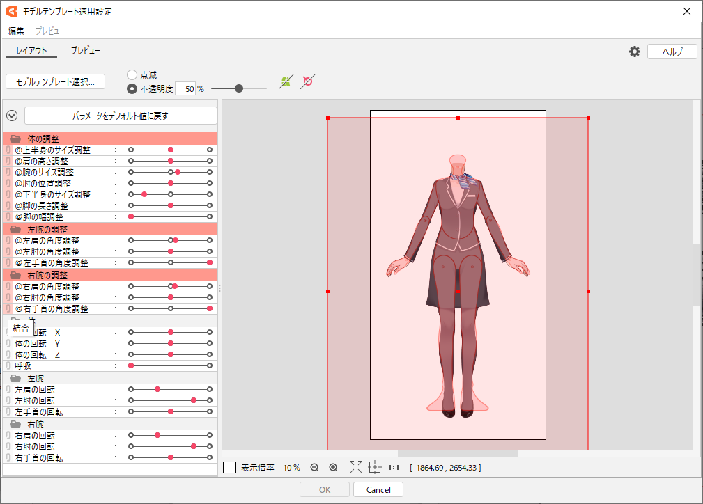
Model template application settings
Set how the template will be applied to the model to which it will be applied.
After selecting a model template in [Model Template Selection], the [Model template application settings] dialog box will appear.
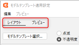
[Model template application settings] includes the [Layout] tab and the [Preview] tab, which can be switched.
Information on applying a model template is saved even after the dialog box is closed, as long as the template and the model to which it is applied are identical.
Select [Yes (Y)] to reflect the saved application information when the dialog box is reopened.
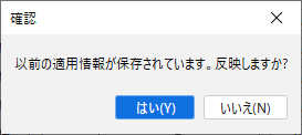
The settings are reset when the editor is closed.
Layout
The selected ArtMesh and the template model are superimposed.
Matching the position and size of the template model improves application accuracy.
Basic layout operations
| Operation | Description |
|---|---|
| Shortcut key [F] | Toggle between blinking and fixed opacity of the model. |
| Drag the model | Move the model. |
| Right-drag the model | Enlarge/reduce the model with the clicked position as the center. |
| Click on the model | Display the bounding box. Clicking outside the bounding box will make the box disappear. |
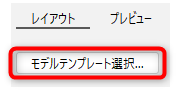
Change template model
Clicking the [Model template selection] button opens the [Model template selection] dialog box where you can change the model.
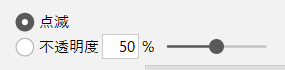
Switch display method
Toggle between blinking the model or displaying it at any opacity.
Opacity can be specified by entering a numerical value or moving the slider.
Show/hide deformers
Shows/hides deformers set in the template model.
This is useful for checking deformer overhangs and deformer positions.
Parameter operation
Manipulate the adjustment parameters marked with “@” to adjust the position and angle of the model.
See “Creating/exporting model templates” for information on parameters for adjustment.
Matching positions and angles with normal parameters may change the appearance of the model to which they are applied.
It is recommended to use the adjustment parameters to match the position and angle.
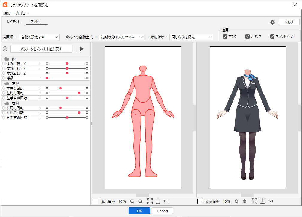
Preview
The template model (on the left side) is displayed side by side with the model to which the template is applied (on the right side), allowing the user to see the actual movement of the model after the template is applied.
Here you can also make minor adjustments regarding the application.
Basic Operation of Preview
| Operation | Description |
|---|---|
| Shortcut key [F] | Toggle playback and stop of motion. |
| Shortcut key [S] | Execute [Match selected elements]. |
| Hover the mouse cursor over the model | The polygon of the ArtMesh at the very front of the cursor position is highlighted, and the mapping state can also be checked. |
| Click on part of the model | The ArtMesh at the very front of the cursor position is selected. This also pops up a list of the mapping states of the ArtMesh at the cursor position. |
Confirmation of movement
Clicking the playback/stop button will automatically play the motion.
Some parts of the body may not automatically play back motion. In this case, manipulate the parameters directly.
Draw order
Set how the draw order of the ArtMesh is changed.
| Item | Description |
|---|---|
| Match the template | The same draw order as the mapped ArtMesh is set. |
| Set automatically | The draw order is automatically set to maintain the appearance before the template is applied. |
| Do not change | Keep the draw order before the template is applied. However, if the order of the parts is changed, the actual order in which the ArtMesh is drawn may change. |
Automatic mesh division
Set the mesh division method.
| Item | Description |
|---|---|
| All meshes | Automatically splits all ArtMesh polygons. |
| Initial mesh only | Only ArtMeshes in their initial state or ArtMeshes with four vertices are automatically divided. |
| Not split | Preserves the state of the mesh before the template is applied. |
Mapping
The ArtMesh is automatically mapped when [Preview] is displayed or the various settings are changed.
This item sets the method for that automatic mapping.
| Item | Description |
|---|---|
| Same name preferred | Preferentially maps ArtMeshes with the same name to each other. If there is no ArtMesh with the same name, the same process as in [Match position and shape] is used to map it. |
| Match position and shape | Maps the ArtMesh based on the position and size of the model as adjusted in [Layout]. |
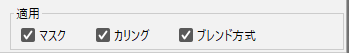
Application of the mask, culling, and blending methods
Individually select whether to enable or disable the application of the mask, culling, and blending methods.
Selected Element Mapping
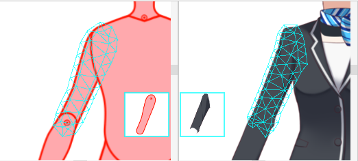
Parts of the template model are automatically mapped to the corresponding parts of the model to which it is applied. (It is also possible to give priority to mappings between ArtMeshes with the same name.)
Hovering the mouse over an ArtMesh highlights the polygon and displays a thumbnail of the corresponding ArtMesh in the center of the view.
Manual mapping of selected elements
To perform the mapping manually, select the ArtMesh of the template model on the left, and then select the ArtMesh you want to map to the model to which the template will be applied on the right.
When the dialog box appears, click on [Match selected elements] to map each part.
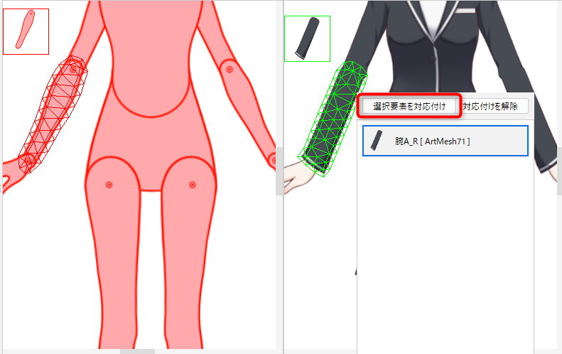
ArtMeshes that cannot be selected due to the draw order are displayed in a pop-up menu by clicking near their location.
Click on any ArtMesh in the menu to select it.
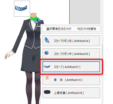
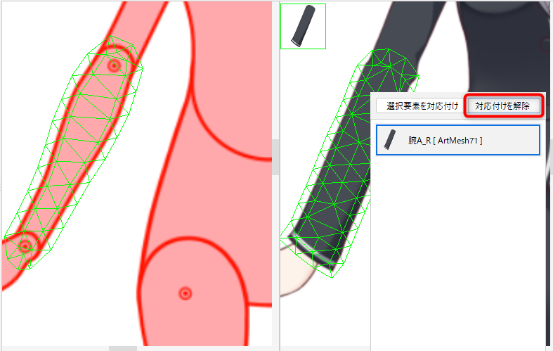
Unmapping
If you want to cancel the unintended mapping, select the target ArtMesh of the model on the right to which you want to apply.
When the dialog box appears, click [Unmapping] to remove the mapping.
Templates are not applied to ArtMeshes that have been unmapped.
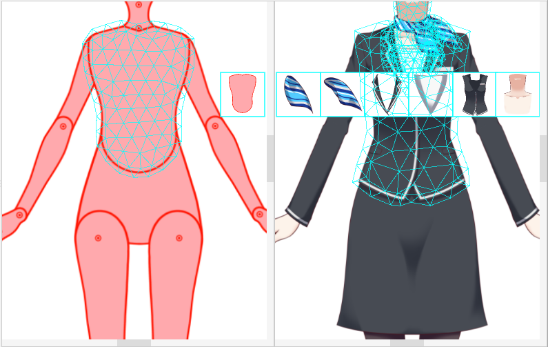
Sometimes multiple ArtMeshes are unintentionally mapped, as in the scarf of the model to which they are applied on the right in the figure below.
In this case, select the target of the template model on the left and click [Unmapping] to remove all mapping.
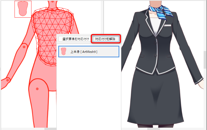
TIPS
If performed from the pop-up menu of the template model, unmapping will remove all mapping for the currently selected ArtMesh.
If performed from the pop-up menu of the model to which the template is applied, it will unmap that ArtMesh.
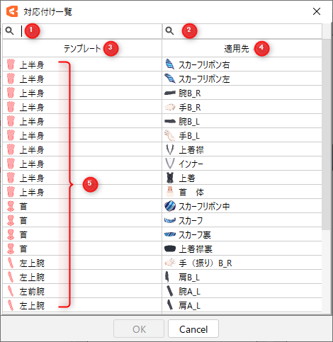
Mapping list
You can check and change the mapping statuses in the list.
Open the dialog box by selecting [Mapping list] in the [Preview] menu.
| Number | Item | Description |
|---|---|---|
| 1 | Template search box | You can search by name or ID. |
| 2 | Search box for application destinations | You can search by name or ID. |
| 3 | Template | Click to sort the template model ArtMeshes in reverse order. |
| 4 | Application destination | Click to sort the application destination model ArtMeshes in reverse order. |
| 5 | Template ArtMesh list | Click to display a combo box that can be mapped to any ArtMesh. Select “-” to cancel the mapping. |
To return the mapping to its initial state, select [Restore mapping to initial state] in the [Preview] menu.
Advanced Settings
Clicking the gear button in the [Model template application settings] dialog box opens the [Advanced Settings] dialog box.
Advanced settings allow you to set how parameters are overwritten, the label color of elements to be added, and more.
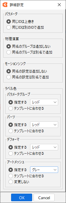
Parameters
Set the handling of IDs for parameters to be added to the model to which they will be applied.
The same ID is overwritten:
If a parameter with the same ID as the template is already included in the model to which it is applied, the template parameter is integrated into the parameter of the model to which it is applied.
As an exception, if the IDs of the regular and blend shape parameters are the same, the process is the same as [The same ID is added with another ID].
The same ID is added with another ID:
If a parameter with the same ID as the template is already included in the model to which it is applied, the ID of the parameter in the template model is changed and added as a separate parameter.
TIPS
All parameters in one model have different IDs.
Therefore, if a parameter with the same ID as the template is already included in the model to which it is applied, the parameter cannot be added without changing the ID.
Physics
Set the handling of physics groups to be added to the model to which they are applied.
Groups with the same name will not be added:
If a physics group with the same group name as the template is already included in the model to which it is applied, it will not be added.
Groups with the same name are added under different names:
If a physics group with the same group name as the template is already included in the model to which it is applied, it is added under another name.
Motion-sync
Set the handling of motion-sync settings to be added to the model to which they will be applied.
Settings with the same name will not be added:
If a motion-sync setting with the same name as the template is already included in the model to which it will be applied, it will not be added.
Settings with the same name are added under different names:
If a motion-sync setting with the same name as the template is already included in the model to which it will be applied, it will be added under a different name.
Label color
Set the label color of the element to be added to the model to which it will be applied.
There are four elements to be added: “parameter groups,” “parts,” “deformers,” and “ArtMeshes.”
Designation:
Change the label color to the specified color.
Match the template:
Reflects the label color set in the template.
Do not change:
Does not change the label color.
Only an ArtMesh has this setting.