ArtPath Auto Generation
Updated: 12/12/2019
ArtPath Auto Generation is a function that automatically creates an ArtPath from “line” and “fill” information in hand-drawn images.
In order to accurately reproduce line art in an ArtPath, it is necessary to prepare original PSDs that have been separated into materials.
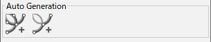
Auto Generation ArtPath Dialog
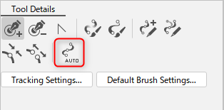
Click on [Open Auto Generation ArtPath Dialog] in the [Tool Details] palette to open the Auto Generation ArtPath Dialog box.
It can also be displayed from the [Modeling] menu -> [ArtPath] -> [Open Auto Generation ArtPath Dialog].
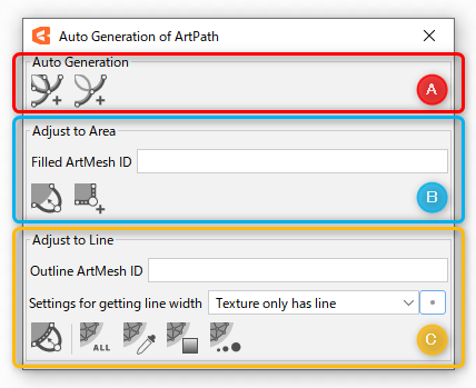
A: Auto Generation
| Name | Description |
|---|---|
| Automatic generation from a single ArtMesh | This function automatically generates an ArtPath around the perimeter of a single selected ArtMesh. |
| Automatic generation from multiple ArtMeshes | This function automatically generates an ArtPath around the perimeter of multiple selected ArtMeshes. |
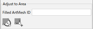
B: Adjust to Area
| Paint ArtMesh ID | Specify the ArtMesh ID of the target fill when performing the [Adjust to Area] function. If there are multiple IDs, they are separated by “,” for each ID. Note: This ID is not recorded in the object. Note: If this field is not filled in, a substitute value can be provided by selecting the target ArtMesh and ArtPath. |
| Follow along the filled ArtMesh | The control points are automatically repositioned to align with the filled ArtMesh. |
| Add control points to align with the ArtMesh | Control points are automatically added where control points are missing. For basic operations such as how to create an ArtPath, see “ArtPath Adjustment.” |
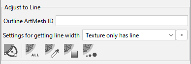
C: Adjust to Line
| ArtMesh ID for Line Art | Specify the ArtMesh ID of the target line art when the [Adjust to Line] function is performed. If there are multiple IDs, they are separated by “,” for each ID. Note: This ID is not recorded in the object. Note: If this field is not filled in, a substitute value can be provided by selecting the target ArtMesh and ArtPath. |
| Settings for getting line width | This setting is used to retrieve information from the ArtMesh specified by the ArtMesh ID of the line art. Line-only textures Line + fill texture (deprecated) |
| Settings for getting line width | Note: Reconfiguration from the default values is typically not necessary. Color change threshold: The default setting is 0.1. The smaller the number, the wider the range of colors will be considered the same color. Maximum width considered to be a line: The default setting is 5px. Minimum value to be considered as transparent: The default setting is 0%. Ignore the invisible point: Control points with 0 opacity or 0 line width are excluded from the automatic setting. |
| Follow along the line of the ArtMesh | The control points are automatically repositioned to follow the line ArtMesh. Note: Please note that using the reflect function while the line art and control points are misaligned will result in poor reproduction. |
| Highlight everything | The “Color,” “Opacity,” and “Line Width” of the line ArtMesh are reflected in the ArtPath all at once. |
| Highlight color | The “Color” of the line ArtMesh is reflected in the ArtPath. |
| Highlight opacity | The “Opacity” of the line ArtMesh is reflected in the ArtPath. |
| Highlight line width | The “Line Width” of the line ArtMesh is reflected in the ArtPath. |
ArtPath Auto Generation
Preparation of original PSD
It is necessary to separate the “line art” and “fill” in the PSD, which is the source to be reproduced in the ArtPath.
For example, if it is a contour, divide it into “contour line” and “contour fill.”
The following table introduces the procedure for creating an ArtPath from “line art” and “fill” ArtMesh, respectively.
| (1) Based on the “fill” ArtMesh information Automatic ArtPath generation | (2) Based on the “fill” ArtMesh information Match the ArtPath to the position of the control points in the source image | (3) Based on the ArtMesh information in the “line art” ArtPath reflects the line information of the ArtMesh | (4) Based on the “line art” ArtMesh information Brush information is reflected in the ArtPath |
 |  |  |  |
 |  |  |  |
Detailed procedures are presented in order starting in the next section, using the “contour” as an example.
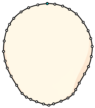
(1) Automatic generation of ArtPath
ArtPaths are automatically generated based on the ArtMesh information in “Fill.”
| Number | Images | Details |
|---|---|---|
| (1) | 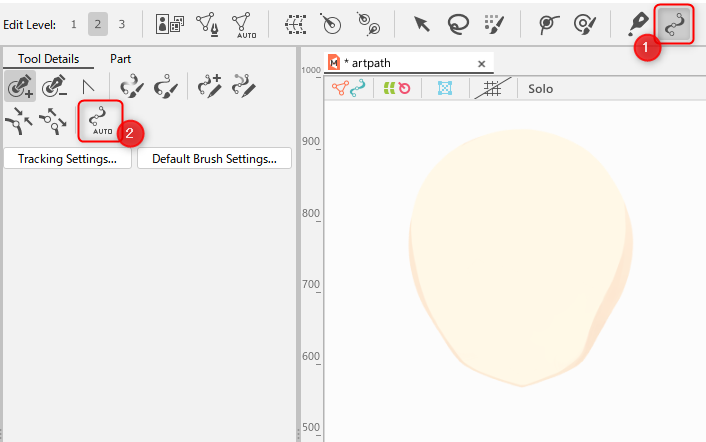 | Select [ArtPath Tools] (1) and click [Auto Generation ArtPath Dialog] (2) to open the dialog box. |
| (2) | 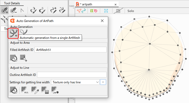 | Select the “fill mesh” for which you want to create an ArtPath, and select [Automatic generation from a single ArtMesh] from the Auto Generate icon. If you want to create an ArtPath from multiple ArtMeshes, select [Automatic generation from multiple ArtMeshes]. |
| (3) | 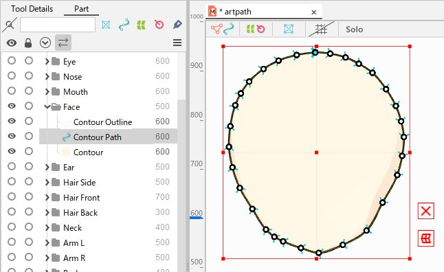 | An ArtPath is automatically generated around the perimeter of the mesh. Note: In the case of automatic generation, the ID is automatically inserted into the [Paint ArtMesh ID] field in the [Auto Generation ArtPath Dialog]. |
The next section describes the process of matching the generated ArtPath to the paint ArtMesh shape.
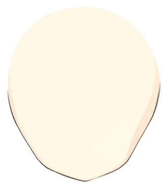
(2) Match the ArtPath to the position of the control point in the source image
Based on the “paint ArtMesh” information, the ArtPath is aligned with the control points in the source image.
| Number | Images | Details |
|---|---|---|
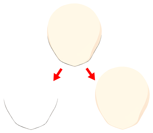
| (1) | 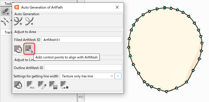 | If the number or position of control points in the automatically generated ArtPath is insufficient to follow the fill ArtMesh, use the [Add control points to align with ArtMesh] function to adjust the position of the control points. Note: The automatically generated ArtPath will be created with the [Close ArtPath] checkbox unchecked. |
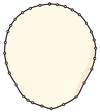
| (2) |  | After the control points have been adjusted, use [Follow along the filled ArtMesh]. Note: In the image on the left, the control points are intentionally separated for clarity. If the generated ArtPath does not follow the filled ArtMesh well, the number of control points or the distances between control points may not be proper, so adjust and redo accordingly. Note: When the distance between control points is too close together, or when the distance from the outer edge of the paint ArtMesh to the control points is too far apart, it may not follow the paint. |
See “ArtPath Adjustment” for basic operations for manually adjusting the ArtPath.
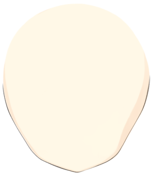
(3) Reflect mesh line information in the ArtPath
The line information of the ArtMesh is reflected in the ArtPath on the basis of the “Line Drawing ArtMesh” information.
| Number | Images | Details |
|---|---|---|
| (1) |  | Select the target ArtMesh and ArtPath you want to use as the source of line information (A), or specify the [ArtMesh ID for Line Art] in the [Auto Generation ArtPath Dialog] (B), and then click [Follow along the line of the ArtMesh]. Note: In the [Settings for getting line width], select Line-only textures as the basic setting. Check that the position of the control points of the ArtPath along the line art are approximately aligned with the center of the line art’s ArtMesh. |
| (2) |  | The “Color,” “Opacity,” and “Line Width” of the line ArtMesh are reflected in the ArtPath. |
(4) Reflect brush information in the ArtPath
Brush texture can be given to an ArtPath by setting a brush.
| Number | Images | Details |
|---|---|---|
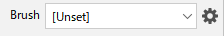
| (1) | 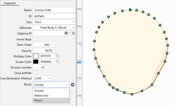 | Select the ArtPath and select any line setting from the brushes in the [Inspector] palette. |
| (2) | | The selected brush texture is reflected in the ArtPath. |
If you want to adjust brush textures more finely or add your own brushes, see “ArtPath Brush Editing.”