Edit Mesh manually
Updated: 05/14/2026
There are two types of mesh editing: “Auto Generation,” which can be generated automatically by simply specifying values related to the density of points, and “Edit manually,” in which points can be edited by clicking them one by one.
On this page you will learn how to manually edit the ArtMesh.
See “Automatic Mesh generator” for details on auto generation.
Edit Mesh manually
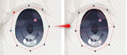
Manual editing of the mesh allows the positions of the vertices to be edited one at a time.
For facial parts such as eyelashes and mouth area, it is recommended to manually edit the ArtMesh to a suitable mesh for deformation in order to apply detailed deformation to the ArtMesh.
In the tutorial video “2. Prepare to move the illustration,” we introduce the recommended mesh-mapping for each part, so please also take a look at that.
Basic manual editing operations
Running mesh edit mode:
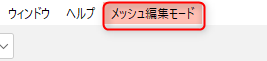
Select the ArtMesh and click [Edit Mesh manually] on the toolbar to switch to Mesh Edit mode.
Note: You can also use the shortcut [Ctrl + E] or double-click the ArtMesh to switch to this mode.
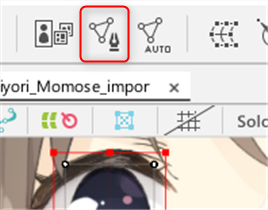
The display on the view switches to [Mesh Edit mode], allowing you to add, delete, and otherwise edit vertices.
Tips
From Environment settings, you can change the setting so that double-clicking on an ArtMesh does not enter Mesh Edit mode. See “Environment settings” for details. Also, double-clicking on an ArtMesh while using the Deform Brush tool does not switch to Mesh Edit mode.
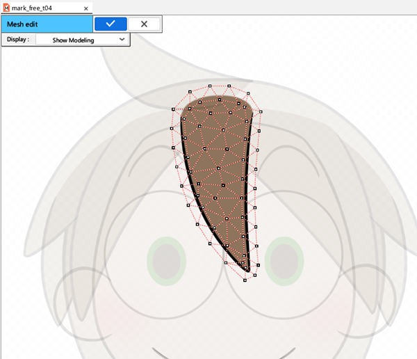
Exiting mesh edit mode:
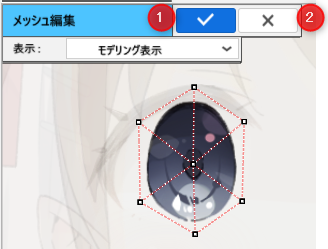
To complete editing, click the check mark button (1) shown in the image below or execute the shortcut [Ctrl + E].
To cancel editing, click the Close button (2) shown in the image below or press the [Esc] key.
Tips
It is also possible to select two ArtMeshes and switch to [Mesh Edit mode]. You can use this method when setting the glue.
In this case, you can edit the two selected ArtMeshes simultaneously without having to switch modes each time or create meshes of the same shape in exactly the same position.
See “Glue” for more information.
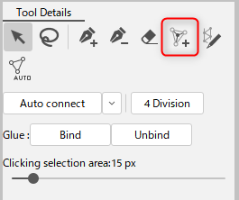
Mesh Edit Tools
After switching to Mesh Edit mode, tools for mesh editing can be selected from the [Tool Details] palette.
 | Select/Edit |
 | Lasso |
 | Add Vertex |
 | Delete Vertex/Edges (line) |
 | Drag to clear polygon Note: You can change the range using [B] + dragging. |
 | Add points |
 | Stroke mesh-mapping (beta) |
| You can also open an auto-generated dialog box during manual editing. See “Automatic Mesh generator” for details on auto generation. | |
| Reset mesh Restore the mesh to the state immediately after the ArtMesh is created. | |
| Auto connect | Generates polygons, which are the smallest elements that make up a mesh. The following options can be selected from the buttons on the right. Mesh reconstruction: If enabled, it redraws the mesh line considering only the vertices. If you want to keep the lines you have constructed, disable it. Protect Edge exterior: If enabled, it will automatically generate while keeping the outer perimeter. This is effective when used with irregularly-shaped textures (eyelashes, hair, etc.) because it prevents excess lines from being tied together. To perform auto generation with “Keep perimeter” enabled, all the perimeters of the vertices must be connected beforehand. |
| Quartering | The mesh is divided into four parts while maintaining the shape. |
| Bind/Unbind | Bind/unbind “Glue.” |
| Selection range on click | If a vertex is difficult to select, increase the numerical value to make it easier to select. |
| Mirror edit | Edit vertices and edges in a symmetrical manner along a straight line. |
Manual editing details
Add Vertex
With the [Add Vertex] tool selected from the [Tool details] palette, click on the canvas to add vertices.
After a vertex is added, the edge (line) is grayed out until the next vertex is added, at which point clicking automatically connects the vertices.

To add a single vertex, deselect (Esc by default) and click.
You can perform the same operation by pressing Ctrl before adding a vertex.
If a vertex is added across an already existing edge, the edge is not connected and becomes a single vertex.

To add a vertex without changing the focus of the vertex, hold down the Shift key and click.
This is useful when you want to add radial edges.
However, it works only on the light blue lines (see below).
A mesh is a collection of triangular “polygons.”
Therefore, to construct a mesh, all vertices must be connected by edges and the smallest unit must be a triangle.
Unconnected vertices are connected by light blue lines.
To connect them, click the [Auto connect] button in the [Tool Details] palette or press Ctrl + R.
Deleting vertices or edges
To delete a vertex, the following methods are available.
- Select a vertex with the [Select/Edit] or [Lasso] tool, and then press the [Delete] or [Back space] key.
- In the [Add vertex] tool, hold down the Alt key and click on a vertex.
- Click on a vertex with the [Delete vertex/edges (line)] tool.
- Click on a vertex with the [Drag to clear polygon] tool. This is useful for deleting a wide range of vertices.
To delete an edge, click on the edge area with the [Drag to clear polygon] tool.
Clicking or dragging while holding down the Alt key deletes only edges without affecting vertices.
Selecting vertices
To select a vertex, use the following tools.
[Select/Edit] tool
- Click on a vertex to select it.
- Shift-click to select multiple vertices.
- Drag to select a wide area with a rectangle.
- You can select multiple ranges by holding down the Shift key and dragging.
[Lasso] tool
- Click on a vertex to select it.
- Shift-click to select multiple vertices.
- Drag to select a wide area with a lasso.
- You can select multiple ranges by holding down the Shift key and dragging.
[Add vertex] tool
- You can select a vertex by clicking on a vertex that has already been created.
- Holding down the Shift key while clicking allows you to select multiple vertices while drawing edges.
Moving a vertex
Moving vertices does not affect the texture; only the shape of the mesh can be edited.
The [Select] Tool can be used to move selected vertices as follows.
- Drag to move a vertex.
- Hold down the Shift key and drag to move horizontally or vertically.
- Drag the center of the bounding box that appears when multiple vertices are selected to move them together.
- Dragging the red dot around the perimeter of the bounding box, which appears when multiple vertices are selected, allows you to move the vertices while expanding or contracting them.
(Holding down the Shift key will expand or contract them while maintaining the aspect ratio; holding down the Alt key will expand or contract them with respect to the center.) - You can rotate multiple vertices by dragging a part other than the red dot around the perimeter of the bounding box that appears when multiple vertices are selected.
Merge vertices
[Merge Vertices] combines already struck vertices and their associated edges into a single vertex.
With multiple vertices selected, right-click on the canvas and select [Merge Vertices].
You can also choose from the menu.
Undo
Press Ctrl + Z to return to the previous operation stage (including the vertex selection operation).
Redo
Press Ctrl + Y to redo the undo operation (including the vertex selection operation).
Menu
After switching to mesh edit mode, the menu bar will display [Mesh Edit mode].
See “Mesh Edit mode menu” for details.
Add points
Select [Add points].
The icon will change to a brush icon. Drag the brush over the mesh as if tracing, and the vertices will be re-divided into smaller pieces. You can increase the number of vertices.
This is useful when you want to increase vertices in a section.
Stroke mesh-mapping (beta)
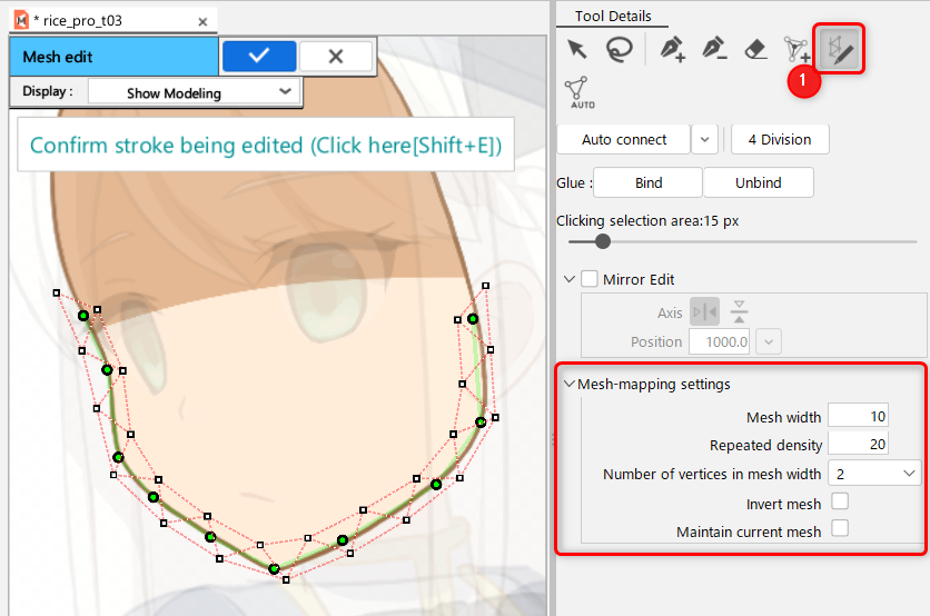
In [Mesh Edit mode], select the [Stroke Mesh-mapping] icon (1).
Dragging the canvas creates a path from which a mesh can be created.
Once a path is created, it can also be redrawn by dragging it again.
The path can be adjusted by dragging, and the mesh will also be updated.
Operation method:
Control point-related operations are described below.
| Operation | Description |
|---|---|
| Click | Add control points on the stroke line. |
| [Alt] + click control point | Delete a control point. |
| Drag a control point | Move the control point of the stroke. |
| [Shift] + drag | Draw additional strokes. |
| Drag away from the path | Rewrite the stroke. |
Adjusting width
The orange circle is the [width handle].
Operation method:
The following are the operations related to width adjustment.
| Operation | Description |
|---|---|
| [Ctrl] + click | Add an edit point (orange circle) on the stroke line. |
| [Ctrl] + [Alt] + click | Delete edit points. |
| [Ctrl] + drag | Click and drag on the width handles to adjust the line width. |
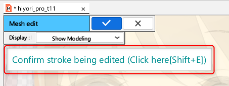
Confirm strokes
If you want to confirm the stroke, click [Confirm stroke being edited] in the upper left corner of the canvas while the path is displayed.
Alternatively, you can click on the [Mesh Edit mode] menu -> [Finish Mesh editing] or press [Shift + E] to confirm.
Cancel strokes
If you want to cancel a stroke before it is finalized, press Delete to cancel.
Also, when switching to other tools such as [Select/Edit], the confirmation dialog box will appear, so select [Cancel].
Mesh-mapping settings
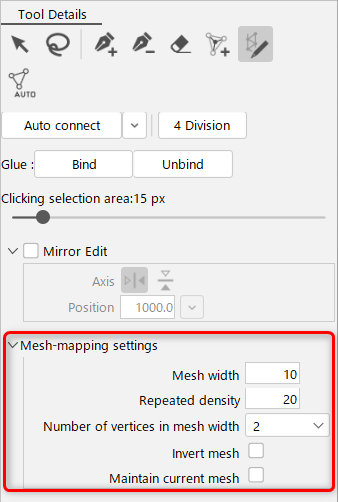
Mesh width
The overall width of the mesh can be adjusted around the stroke.
Repeated density
The spacing between mesh-mappings can be adjusted.
The value is the distance between intervals, so the smaller the value, the narrower the interval, and the larger the value, the wider the interval.
Number of vertices in mesh width
There are three ways to divide the mesh.
1: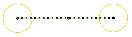
2: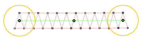
3: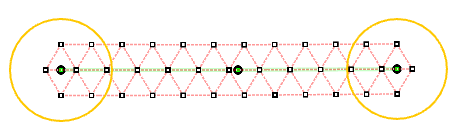
Invert mesh
Flips the direction of the first and last mesh edges when the number of vertices in the mesh width is two.
Maintain current mesh
When unchecked, the overlapping edges and vertices are deleted.
Also, when checked, it is not deleted but maintained.
Menu for stroke mesh-mapping (beta)
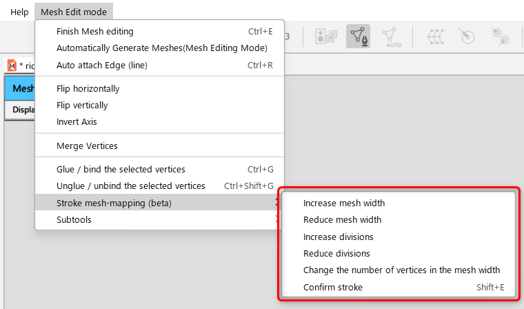
Increase/decrease mesh width
Increase or decrease the overall mesh width.
Increase/decrease division
The repeat spacing increases or decreases as the mesh width spacing changes.
Change the number of vertices in the mesh width
The setting for the number of mesh width vertices is switched in the following order: 1, 2, 3, 1.
Confirm strokes
Finalize the mesh created from the stroke.
Tips
This operation can be set as a shortcut.
Divide the Mesh into 4 Parts
Click the [4-division] button.
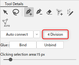
The polygons have been divided into four parts while maintaining the shape of the mesh.
This function is useful when you do not want to change the shape of the mesh, but want to smooth out the movement.
Mirror edit
The Mirror Edit function edits vertices and edges so that they are symmetrical around a straight line axis.
“Flip horizontally” and “Flip vertically” editing is supported.
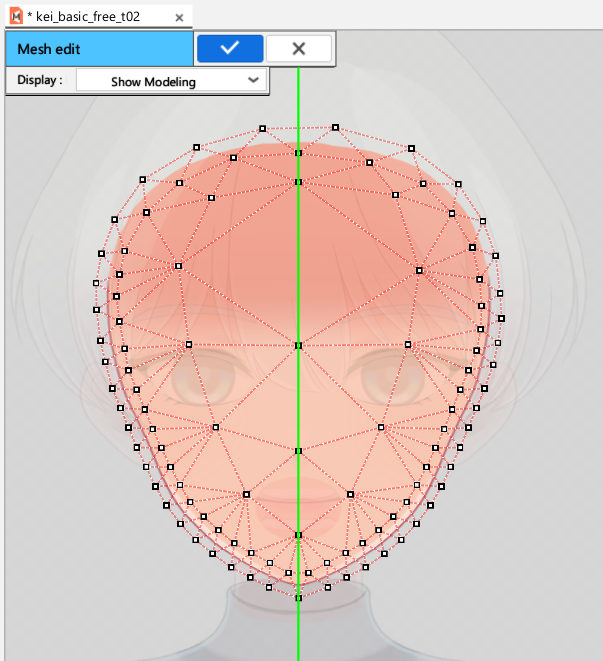
Check the [Mirror Edit] checkbox in the [Tool details] palette.
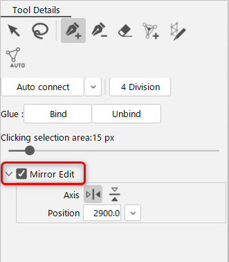
A green axis appears on the canvas.
Specify the axis or position at which you want to place vertices symmetrically.
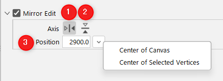
| Number | Description |
|---|---|
| 1 | A “vertical” green axis appears on the canvas. Mirror editing can be performed with “Flip horizontally.” |
| 2 | A “horizontal” green axis appears on the canvas. Mirror editing can be performed with “Flip vertically.” |
| 3 | You can specify the position of the axis. Center of the Canvas: The axis is placed in the center of the canvas. Center of selected vertices: The axis is placed in the center of the selected vertex group. |
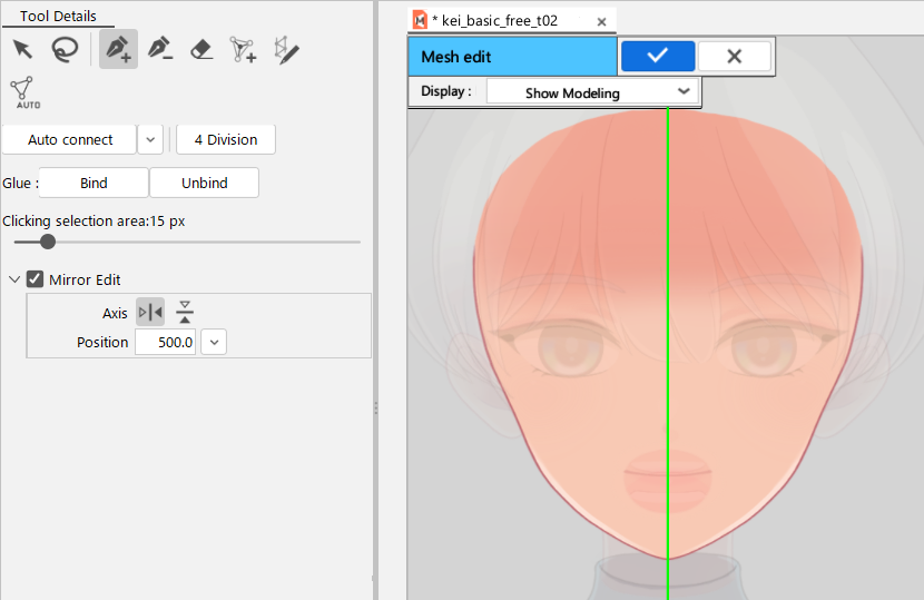
Mirror editing when the “Add vertex” tool is selected
Mirror editing when the “Stroke mesh-mapping (beta)” tool is selected
Display of Mesh Edit Mode
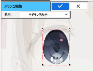
In Mesh Edit mode, you can change the display format of the ArtMesh to be edited.
Switch to a format that is easy to use and edit.
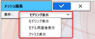
Displaying modeling
Textures other than the ArtMesh being edited will be dimmed.
Displaying model guide image
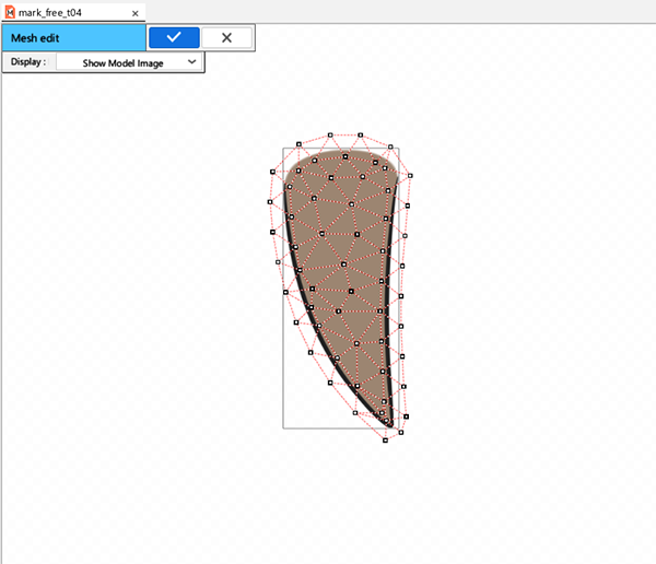
Only the ArtMesh being edited is displayed.
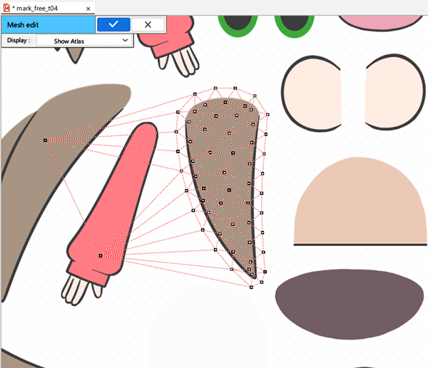
Atlas view

Textures from the Texture Atlas are displayed.
This can be set when a Cubism 2.1 model is loaded or when a texture atlas is created with Cubism 3 or later.
When editing in this view, if the mesh being edited overlaps an adjacent texture, as shown in the figure below, an extra texture will appear on the model.
When using [Atlas View], be careful not to overlap the surrounding textures with the margins.
If there is an unintended texture image displayed on the imported model as shown in the figure below, check for overlapping ArtMeshes in the [Atlas View] or [Texture Atlas] in the [Mesh Edit mode].
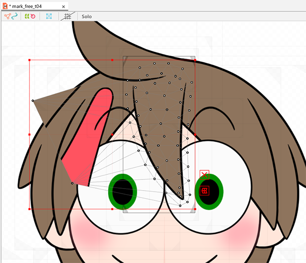
This can be corrected by editing the Mesh in [Atlas View] in [Mesh Edit mode] or by rearranging the ArtMeshes in [Texture Atlas] so that they do not overlap.