About ArtPaths
Updated: 08/17/2023
What is an ArtPath?
An ArtPath is a feature to represent the main lines of an illustration.
The line texture of an illustration can be handled on the model as if it were vector line material, allowing free deformation and color change expression while maintaining the texture and thickness of the line.
Note: The ArtPath function is only available when the target version of the model is “SDK(N/A)/Latest Cubism.”
If you select the ArtPath function in a target version other than the above version, a warning pop-up message will appear, and a cautionary statement will appear in the lower-right corner of the View area.
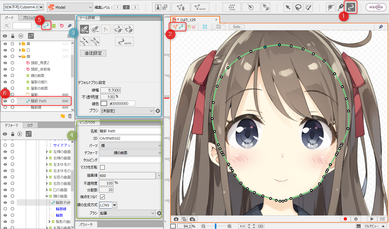
ArtPath Screen Layout
| Number | Name | Details |
|---|---|---|
| (1) | ArtPath Tools | You can create and edit a new ArtPath. |
| (2) | Locking of drawable objects | Only ArtMesh and ArtPath can be shown/hidden and locked on the view. Textures are displayed as they are. |
| (3) | Tool Details | For details on the [Tool Details] palette when selecting an ArtPath, see “Tool Details Palette.” |
| (4) | Inspector | For details on the [Inspector] palette when selecting an ArtPath, see “Inspector Palette.” |
| (5) | Show/hide ArtPaths | Shows/hides the ArtPath in the [Part(s)] palette. |
| (6) | ArtPath | The created ArtPath will be added to the [Part(s)] palette. |
Properties and Types of ArtPaths
“LCNS” and “SNS” are used for the line generation method of the ArtPath.
Each of these changes the shape of the line even when the position of the control point is the same.
See the table below for the differences between them.
| LCNS line | SNS line | |
| Visual differences | 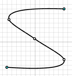 | 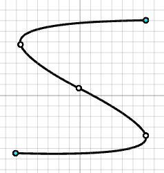 |
| Behavior when moving a control point |  |  |
Sprite method drawing mechanism
This section explains how lines are drawn when an ArtPath is drawn with a sprite method brush.
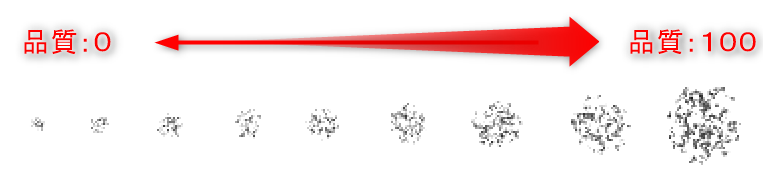
In the sprite method, which uses textures prepared with multiple brush sizes, the texture size chosen depends on the quality value of the brush setting.
The higher the quality, the higher the resolution of the texture selected for smaller line widths.
The lower the quality, the lower the resolution of the texture selected for larger line widths.
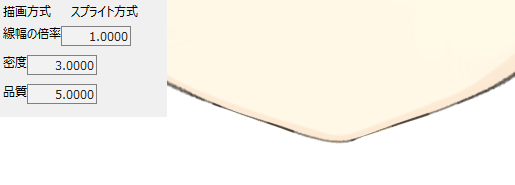
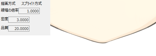
The following are outlines of a sample model Hiyori Momose (video version), adjusted to make it easier to understand how the sprite method drawing works.
| Quality: 5 The textures selected by the line width overlap each other, and areas that look like overlapping ink are drawn. | Quality: 20 This is drawn with smooth brushstrokes. |
 |  |
As you can see, the appearance of the lines may change depending on the quality, so please adjust the values appropriately while looking at the actual ArtPath drawn on the canvas.
For details on the sprite method, see the Sprite Method section of “ArtPath Brush Editing.”
Mesh method drawing mechanism
This section explains how lines are drawn when an ArtPath is created with a mesh method brush.
The mesh method of ArtPath lines changes the drawing mechanism as the number of control points increases.
Below is a mesh method texture that has been adjusted to make the drawing mechanism easier to understand.
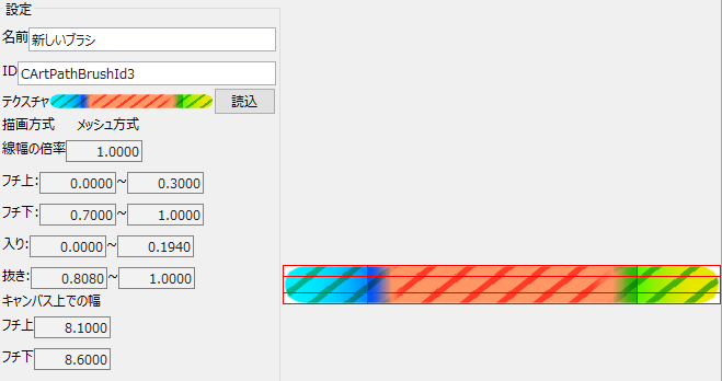
The following figures show how the line changes with the number of control points when a straight line is drawn with this brush.
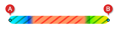
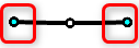
2 points (A-B)
The ratio between control points A-B will be the same as the appearance of the texture. Moving either vertex does not change the ratio of tip begin/end.
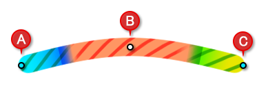
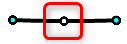
3 points (A-B-C)
The same ratio of brush texture is used as in the 2 points, but the ratio of tip begin/end changes when the position of the control point B, which is in the middle, is moved.
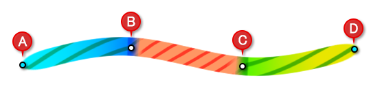
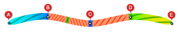
4 points (A-B-C-D)
The line between the first two control points A-B is set as “Tip begin” and the line between the last two points C-D is set as “Tip end.”
For the line between B and C, “Segment” is displayed.
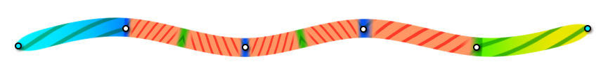
5 points (A-B-C-D-E)
For 5 or more points, the following mechanism is used to draw.
The line between the first two control points A-B is set as “Tip begin” and the line between the last two points D-E is set as “Tip end.”
For the line between B and C, “Segment” and “(reversed left and right) Segment” are displayed.
For the line between C and D, the second and third points counting from the last, “Segment” is displayed.
The mechanism for 6 points or more is the same as the concept for 5 points.
The line between the first two control points is set as “Tip begin” and the line between the last two control points is set as “Tip end.”
The “Segment” is displayed between the second and third control points counting from the last, and “Segment” and “(reversed left and right) Segment” are repeated between the other control points.
For more information on mesh methods, see the Mesh Method section of “ArtPath Brush Editing.”
Expansion and Contraction of ArtPaths
ArtPaths maintain their line widths even when scaled with bounding boxes or deformers.
If you want to change the line width on the model, adjust the line width setting for the control point.
In the Animation View, you can set the ArtPath width magnification from [Placement & Opacity] in the [Property Group].
Note: The width set for the border in the brush settings is maintained even if the magnification is changed.
Note: If the magnification is reduced until the borders touch each other, the magnification of the borders will also be reduced.
About the Display of ArtPaths
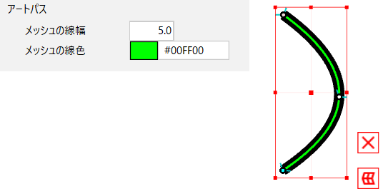
The line width and line color of the ArtPath mesh can be changed.
Open the [File] menu -> [Environment settings].
Under [ArtPath] in [Object style], set the [Mesh Line Width] and [Mesh Line Color].
For more information on environment settings, see “Environment settings.”
Control point types
 | The control points of the ArtPath that are not selected are displayed in white. |
 | The control points of the ArtPath with start and end points set are displayed in light blue. |
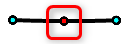 | The control points of the selected ArtPath are displayed in red. |
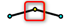 | The control points of the ArtPath with fold lines are displayed in yellow. |
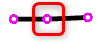 | The control points of ArtPaths that have been set with tracking are displayed in pink. |
How to Create an ArtPath
There are two main ways to create an ArtPath.
ArtPath auto generation function
This is a method to reproduce the “main line” as an ArtPath on the model from data that has the “main line” and “fill” in the source PSD.
See “ArtPath Auto Generation” for details.
ArtPath manual generation function
This is a method for freely creating line drawings with ArtPaths in the model.
For more information, see “ArtPath Manual Creation.”