ArtPath adjustment
Updated: 12/17/2024
Basic ArtPath Adjustment
This is how to make adjustments to the ArtPath and control points from the [Tool Details] palette and [Inspector] palette.
For a detailed description of how to use the ArtPath’s [Tool Details] palette, see “Tool Details.”
For a detailed description of how to use the [Inspector] palette for ArtPath, see “Inspector Palette.”
Add control point
When creating a new ArtPath, use this to add more control points to the ArtPath.
Select the [Add control point] icon in the [Tool Details] palette and click where you want to add the control point.
Delete control point
Use this to delete control points in the ArtPath.
Select the [Delete control point] icon in the [Tool Details] palette and click on the control point you want to delete.
Control point fold line
Use this when you want the control points of an ArtPath to be fold lines.
Select the [Control point fold line] icon in the [Tool Details] palette and click on the control point you want to make a bend.
Or, while a control point is selected, tick the checkbox for the fold line in the lower “Control Point Settings” in the [Inspector] palette.
Join ArtPaths
This function connects the control points at the ends of two ArtPaths to form a single ArtPath.
Select the endpoint of the first ArtPath, place the cursor over the endpoint of the second ArtPath you wish to connect, and its control point will be automatically selected. Click the control point to connect the ArtPaths.

Also, if you Alt + click to connect control points, they are merged at the second selected endpoint.
Split ArtPath
Click the ArtPath line where you want to cut it off.

Note: Connecting/disconnecting ArtPaths may change the shape of the line depending on the shape.
In such cases, manually adjust the control points to the desired shape.
Adjust the opacity set for the control point
Use this when you want to change the opacity of a control point in an ArtPath.
Select the [Adjust opacity set on control point] icon in the [Tool Details] palette and drag the control point whose opacity you want to change.
Drag: Increase opacity
Alt + drag: Reduce opacity
B + drag: Change brush size
Alternatively, changes can be made from the Opacity % value in the “Control Point Settings” at the bottom of the [Inspector] palette while a control point is selected.
Adjust the thickness set for the control point
Use this when you want to change the thickness of the control points in the ArtPath.
Select the [Adjust the thickness set on control point] icon in the [Tool Details] palette and drag the control point whose thickness you want to adjust.
Drag: Increase line width
Alt + drag: Reduce line width
B + drag: Change brush size
Alternatively, while a control point is selected, it can be changed from the pixel value of the line width in the “Control Point Settings” at the bottom of the [Inspector] palette.
If you want to set the line width and color for all ArtPath lines at once, after selecting all the control points of the ArtPath you want to adjust with the [Arrow Selection Tool], change the desired settings from “Control Point Settings” at the bottom of the [Inspector] palette.
Tips
When the ArtPath tool is selected, selecting the ArtPath will focus on the control point.
Therefore, if you want to move all the control points together, you can hold down “Ctrl” and drag them.
Division number
The higher the number of divisions in the “Division number” under “Control Point Settings” in the [Inspector] palette, the smoother the ArtPath line will curve.
The default value is 20.
Note: The higher the number of divisions, the more it affects the Editor’s overall performance.
Close ArtPath
Select the “Close ArtPath” checkbox under “Control point settings” in the [Inspector] palette to automatically interpolate the edges of the ArtPath lines to look like they are connected when there are three or more control points.
(If there are two or fewer control points, selecting the checkbox does not change the appearance.)
Note: When connecting the end points, the shape of the line may change depending on the shape, so please adjust the control points manually and adjust the shape as desired.
Line Generation Method LCNS/SNS
You can choose to calculate interpolation of lines between control points in the ArtPath.
For a summary of each feature, see “ArtPath: Properties and Types of ArtPaths.”
ArtPath Parameter Control
The ArtPath can also be parameterized like regular objects.
The elements that can be set are the “position,” “Line Width,” “Line Color,” and “Opacity” of the control point.
ArtPath Adjustments Available Only from the [ArtPath] Menu
The following is a list of what you can do with the ArtPath from the [ArtPath] menu.
Add a point in the middle of all control points
This function adds a point in the middle of all control points of the ArtPath.
Points can be added by clicking [Modeling] -> [ArtPath] -> [Add a point in the segment of all control points].
Add a point in the middle of the selected control points
This function adds a point in the middle of the selected control points of the ArtPath.
Points can be added by clicking [Modeling] -> [ArtPath] -> [Add a point in the segment of the selected control point].
Create Deform Paths from ArtPath
This function can automatically generate control points for deform paths at the locations of the control points of the ArtPath.
Select the ArtPath and ArtMesh, then select [Modeling] menu -> [ArtPath] -> [Create Deform Path from ArtPath] to create a deform path on the ArtMesh side.
When adjusting the ArtPath with the generated deform path, keep both the ArtPath and the ArtMesh selected while moving the ArtPath.
The basics are the same as for normal deform paths. See “Deform Paths” for details.
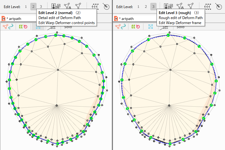
Note: Deform paths are generated for each of Level edits 2 and 3.
Level edit 2 generates the same number of control points for the deform path as the number of control points for the ArtPath.
Level edit 3 generates half the number of control points of the ArtPath as the control points of the deform path.
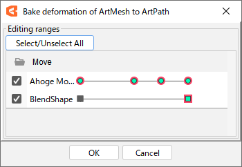
Bake deformation of ArtMesh to ArtPath
This function allows you to burn in a shape so that the ArtPath follows the deformation applied to the ArtMesh.
Select the ArtMesh and ArtPath, then click [Modeling] menu -> [ArtPath] > [Bake deformation of ArtMesh to ArtPath] to generate the same keyforms for the ArtPath as for the ArtMesh.
Note: The deformation is reflected according to the positional relationship between the ArtMesh and ArtPath.
Tips
[Bake deformation of ArtMesh to ArtPath] can also be used for [Blend Shape].
Tracking Settings
Follow all / Cancel all
Follow selected control points / Release selected control point
This function allows the ArtPath to follow the deformation applied to the ArtMesh in real time.
Select the ArtMesh and ArtPath, then select [Modeling] menu -> [ArtPath] -> [Follow all].
To cancel, select an ArtPath that is being tracked and select [Modeling] menu -> [ArtPath] -> [Cancel all].
This function can also be set for the currently selected control point.
In this case, select [Modeling] menu -> [ArtPath] -> [Follow selected control points / Release selected control point].
Note: The ArtPath line alone cannot be deformed while tracking is in progress. (Color and opacity can be edited while tracking)