Inspector palette
Updated: 08/26/2025
The inspector palette is used to set up ArtMeshes and deformers.
You can change the ID, name, drawing order, opacity, and parts and deformers that belong to it.
What is displayed depends on the type of object selected.
Display When the ArtMesh Is Selected
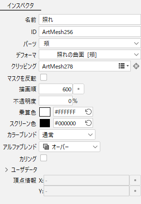
| Item | Details |
| Name | You can change the name of the ArtMesh. Japanese can also be used. |
| ID | Change IDs. Only single-byte alphanumeric characters and _ (underscore symbol) characters can be used. |
| Part(s) | Change the part to which it belongs. [Root Part] indicates that it does not belong to any part. |
| Deformer | Change the deformer to which it belongs. [Root] indicates that it does not belong to any deformer. The name of the part to which the deformer belongs is displayed in parentheses. You can set it to be hidden from “Environment settings.” |
| Clipping ID | Specify the clipping ID. (Set this when the clipping function is used.) |
| Invert Mask | If checked, mask inversion is applied. See “Inverted Mask” for more information. |
| Draw order | Change the order in which ArtMeshes are drawn. Drag within the text box to change the value. You can enter a numeric value directly or specify increments of 10 or 100 from the pop-up menu that appears when you click the [•] button to the right. Alternatively, it can be changed by dragging on the draw order edit bar to the left of the View area. |
| Opacity | Change the opacity of the selected ArtMesh. |
| Multiply Color | Multiply and composite colors on an ArtMesh. |
| Screen Color | Screen composite colors onto an ArtMesh. |
| Color Blend | Change the RGB compositing method for the selected ArtMesh. |
| Alpha Blend | Change the alpha compositing method for the selected ArtMesh. |
| Culling |
Set whether or not the mesh should be drawn when it is turned over. |
| User Data |
Set user data in the ArtMesh. |
| Vertices Info |
The vertex information for the selected object can be displayed and edited in canvas coordinates. |
For more information on ArtMeshes, see “About ArtMeshes.”
Display When the Warp Deformer Is Selected
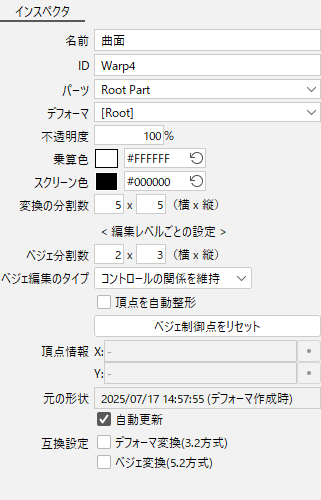
| Item | Details |
| Name | You can change the name of the warp deformer. Japanese can also be used. |
| ID | Change IDs. Only single-byte alphanumeric characters and _ (underscore symbol) characters can be used. |
| Part(s) | Change the parts folder to which it belongs. [Root Part] indicates that it does not belong to any part. |
| Deformer | Change the deformer to which it belongs. [Root] indicates that it does not belong to any deformer. The name of the part to which the deformer belongs is displayed in parentheses. You can set it to be hidden from “Environment settings.” |
| Opacity | Change the opacity of the ArtMesh to which it belongs. |
| Multiply Color | Multiply and composite colors on drawable objects that are child elements of the deformer. |
| Screen Color | Screen composite colors on drawable objects that are child elements of the deformer. |
| Number of conversion divisions | Specify the fineness of the control point. The larger the number, the more deformations follow the deformer shape. |
| Bezier Division number | Specify the fineness of the control point. The larger the number, the more editing points and handles, and the more detailed the deformation, but the more work it takes. |
| Bezier Edit Type | The degree of influence of deformation can be adjusted. |
| Automatic Vertex Shaping | If this item is checked, the division point will always be shaped along the Bezier handle. |
| Reset Bezier controllers | Restores the edited Bezier control points and handles to their original shape along the lattice. |
| Vertices Info |
The vertex information for the selected object can be displayed and edited in canvas coordinates. |
| Original shape |
The original shape is recorded when the warp deformer is created and when the key is added. |
| Compatibility setting |
Deformer conversion (3.2 method): Bezier conversion (5.2 method): |
For more information on warp deformers, see “Warp Deformer.”
Display When the Rotation Deformer Is Selected
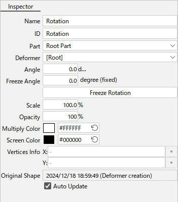
| Item | Details |
| Name | You can change the name of the rotation deformer. Japanese can also be used. |
| ID | Change IDs. Only single-byte alphanumeric characters and _ (underscore symbol) characters can be used. |
| Part(s) | Change the parts folder to which it belongs. [Root Part] indicates that it does not belong to any part. |
| Deformer | Change the deformer to which it belongs. [Root] indicates that it does not belong to any deformer. The name of the part to which the deformer belongs is displayed in parentheses. You can set it to be hidden from “Environment settings.” |
| Angle | Rotate at the specified angle. |
| Standard Angle |
The specified standard angle (angle considered to be 0 degrees) is displayed. This setting is used when the character in the source image is tilted. |
| Scale | Change the magnification of the child elements around the fulcrum. The values are retained and can be changed or restored each time. |
| Opacity | Change the opacity of the ArtMesh belonging to the selected rotation deformer. |
| Multiply Color | Multiply and composite colors on drawable objects that are child elements of the rotation deformer. |
| Screen Color | Screen composite colors on drawable objects that are child elements of the rotation deformer. |
| Vertices Info |
The vertex information for the selected object can be displayed and edited in canvas coordinates. |
| Original shape |
The original shape is recorded when the rotation deformer is created and when the key is added. |
For more information on rotation deformers, see “Rotation Deformer.”
Display When the ArtPath Is Selected
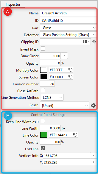
A:
| Item | Details |
| Name | You can change the name of the ArtPath. Japanese can also be used. |
| ID | Change IDs. Only single-byte alphanumeric characters and _ (underscore symbol) characters can be used. |
| Part(s) | Change the parts folder to which it belongs. [Root Part] indicates that it does not belong to any part. |
| Deformer | Change the deformer to which it belongs. [Root] indicates that it does not belong to any deformer. The name of the part to which the deformer belongs is displayed in parentheses. You can set it to be hidden from “Environment settings.” |
| Clipping ID | Specify the clipping ID. (Set this when the clipping function is used.) |
| Invert Mask | If checked, mask inversion is applied. See “Inverted Mask” for more information. |
| Draw order | Change the order in which ArtPaths are drawn. Drag within the text box to change the value. You can enter a numeric value directly or specify increments of 10 or 100 from the pop-up menu that appears when you click the [•] button to the right. Alternatively, it can be changed by dragging on the draw order edit bar to the left of the View area. |
| Opacity | Change the opacity of the selected ArtPath. |
| Multiply Color | Multiply and composite colors on the ArtPath. |
| Screen Color | Screen composite colors onto an ArtPath. |
| Division number | Change the number of divisions in the selected ArtPath. |
| Close ArtPath | If checked, the endpoints of the selected ArtPaths will be connected. |
| Line Generation Method | The line generation method can be selected from “LCNS” or “SNS.” |
| Brush | Brush selection is available. The gear icon opens the ArtPath Brush Settings dialog box. |
B: Control point settings
| Name | Details |
| Keep Line Width as 0 | If checked, a control point with a line width of 0 will remain 0 even if another line width is set for it. |
| Line Width | You can change the line width of selected control points. |
| Line Color | You can change the line color of selected control points. |
| Opacity | You can change the opacity of selected control points. |
| Fold line | If checked, the selected control points will make up a fold line. |
| Vertices Info | Vertex information for the control point is displayed. |
See “About ArtPaths” for more information on ArtPaths.
Display When a Part Is Selected
When a part is selected
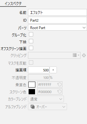
| Item | Details |
|---|---|
| Name | You can change the name of the part. Japanese can also be used. |
| ID | Change IDs. Only single-byte alphanumeric characters and _ (underscore symbol) characters can be used. |
| Part(s) | Change the parts folder to which it belongs. [Root Part] indicates that it does not belong to any part. |
| Grouping | By checking the checkbox, the selected parts are grouped together to create a draw order group. (The icon of the part changes when it is grouped.) |
| Guide Image | By checking the checkbox, the selected part is changed to the part for the guide image. (It is also possible to make multiple parts for the guide image.) |
| Offscreen drawing |
When this checkbox is selected, offscreen drawing is enabled. |
| Draw order | Change the order in which parts are drawn. Drag within the text box to change the value. You can enter a numeric value directly or specify increments of 10 or 100 from the pop-up menu that appears when you click the [•] button to the right. Alternatively, it can be changed by dragging on the draw order edit bar to the left of the View area. |
For more information on parts, see “About Parts.”
When offscreen drawing is set
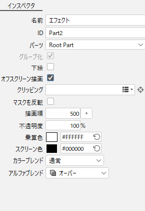
| Item | Details |
|---|---|
| Name | You can change the name of the part. Japanese can also be used. |
| ID | Change IDs. Only single-byte alphanumeric characters and _ (underscore symbol) characters can be used. |
| Part(s) | Change the parts folder to which it belongs. [Root Part] indicates that it does not belong to any part. |
| Grouping | By checking the checkbox, the selected parts are grouped together to create a draw order group. (The icon of the part changes when it is grouped.) |
| Guide Image | By checking the checkbox, the selected part is changed to the part for the guide image. (It is also possible to make multiple parts for the guide image.) |
| Offscreen drawing |
When this checkbox is selected, offscreen drawing is enabled. |
| Clipping ID | Specify the clipping ID. (Set this when the clipping function is used.) |
| Invert Mask | If checked, mask inversion is applied. See “Inverted Mask” for more information. |
| Draw order | Change the order in which parts are drawn. Drag within the text box to change the value. You can enter a numeric value directly or specify increments of 10 or 100 from the pop-up menu that appears when you click the [•] button to the right. Alternatively, it can be changed by dragging on the draw order edit bar to the left of the View area. |
| Opacity | Change the opacity of the selected part. |
| Multiply Color | Multiply and composite colors on parts. |
| Screen Color | Screen composite colors onto a part. |
| Color Blend | Change the compositing method for the RGB of the selected part. |
| Alpha Blend | Change the compositing method for the alpha of the selected part. |
See “Offscreen drawing” for details on offscreen drawing.
Display When the Deform Path Edit Is Selected
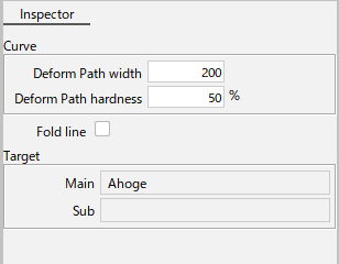
| Item | Details |
|---|---|
| Deform Path width | Change the degree of influence between control points of deform paths. The smaller the value, the closer to inversion the deformation will be. |
| Deform Path hardness | The higher the stiffness ratio, the less likely it is that the mesh shape near the deform paths will deform, making it more likely that this shape will be retained. |
| Fold line | The control points of deform paths will make up a fold line. |
| Main | This is the main ArtMesh used when creating deform paths for a single ArtMesh or multiple ArtMeshes. The color of the mesh changes to purple when deform paths are selected. The deform paths you set can be displayed and edited only when you select Main. |
| Sub | ArtMeshes set outside of the main when deform paths are created for multiple ArtMeshes. The color of the mesh changes to red when a deform paths are selected. When setting deform paths on multiple ArtMeshes, the last selected mesh becomes the main one. |
For more information on deform paths, see “Deform Paths.”
Display When a Glue Is Selected
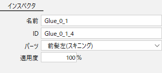
| Item | Details |
|---|---|
| Name | You can change the name of the glue. Japanese can also be used. |
| ID | Change IDs. Only single-byte alphanumeric characters and _ (underscore symbol) characters can be used. |
| Part(s) | Change the parts folder to which it belongs. [Root Part] indicates that it does not belong to any part. |
| Compatibility | The degree of glue application can be changed numerically in a batch. You can also add keys to the parameters and change the applicability for each key. |
For more information on glue, see “Glue.”
Display When a Blend Shape Is Selected
For more information on the [Inspector] palette when using blend shapes, see “Blend Shape.”
Select Lock Behavior
When you lock an object from the [Deformer] or [Part(s)] palettes, the information in the [Inspector] palette is locked.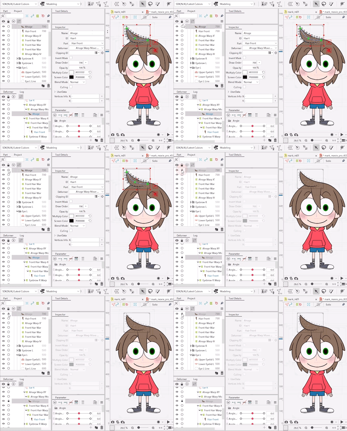
This setting can be enabled/disabled by doing the following.
Open the [File] menu -> [Environment settings].
Under [Window], select/clear the [Lock the inspector when an object is locked] check box.
For more information on environment settings, see “Environment settings.”
Display When the Animation View Is selected
For more information on the [Inspector] palette when using the Animation View, see the following.
When a scene is selected:
See “Scene management and settings.”
When a parameter controller is selected:
See “About the parameter controller.”
