About ArtMeshes
Updated: 08/26/2025
On this page you will learn about ArtMeshes.
What Is an ArtMesh?
PSD images loaded into the model workspace are automatically assigned a mesh for each layer and placed on the canvas.
Each of these is an “ArtMesh.”
In the image below, a set of polygons (mesh) composed of vertices and lines is assigned to the eyebrow image (texture).
By moving each of these vertices, the image can be deformed to create expression and movement.
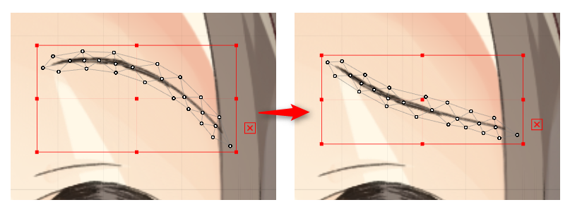
Upon importing a PSD, each layer (or group) in the PSD is automatically placed as an ArtMesh, but if all meshes are very detailed, the data volume will be too large.
Thus, immediately after placement, the ArtMesh consists of a minimum number of vertices.
Note: However, when using videos that do not use the SDK, there is no need to be aware of the data capacity, as it does not affect the data volume.
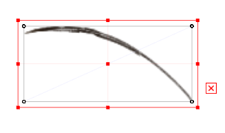
These default state ArtMeshes can be further edited in detail to suit the image you want to deform.
See the “Automatic Mesh Generator” page for more information on how to edit the mesh in detail.
Blend mode
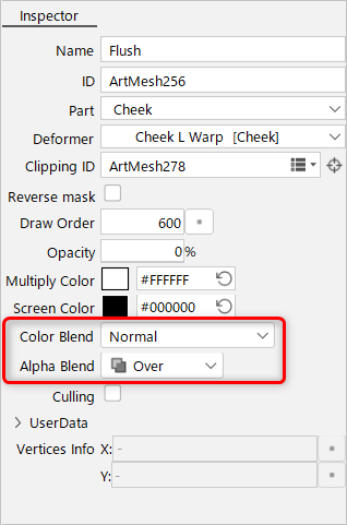
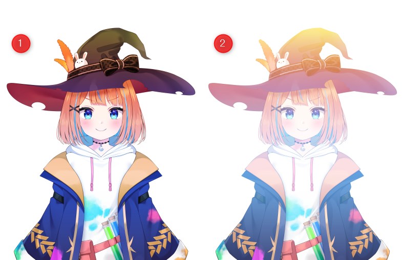
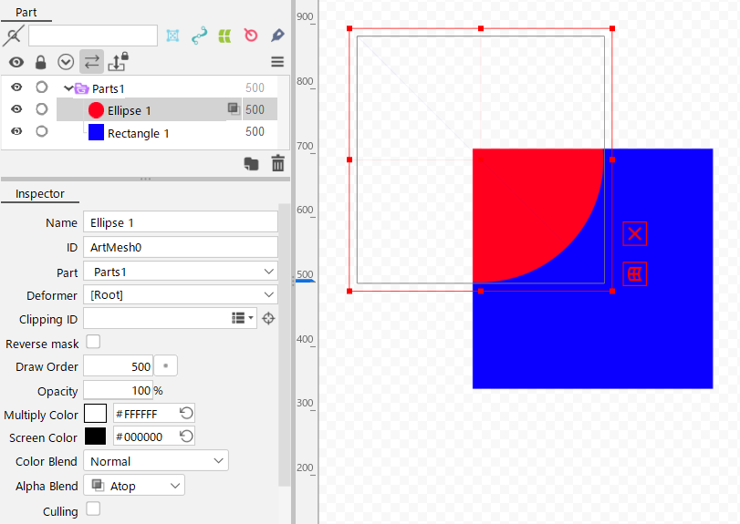
You can specify the compositing methods for RGB and alpha.
By default, the color blend is set to [Normal] and the alpha blend is set to [Over].
See “Blend mode” for details.
| Color Blend (1) Overlay (2) Screen | Alpha Blend |
 |  |
Notes on specifying blend mode
Note that when using blend modes other than “Normal” and “Over,” the appearance may not be accurately reproduced in some environments.
In animation view, for example, the model is drawn and composited on a transparent layer because of the way it is structured, so the appearance of the blend mode may change.
The same applies to:
- Drawing models in the Physics Settings and Model Template Application Settings dialog boxes.
- Exported images and videos (including snapshots).
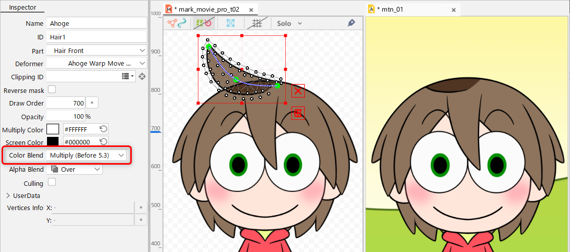
Even in the SDK, the expression may vary depending on the version, platform, off screen usage, shader settings, etc.
Please be sure to check with the actual device before use.
Culling
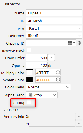
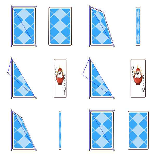
Culling is the function not to draw the backside of polygons.
The default setting is [Off].
| Selected (one sided drawing) Polygons are not drawn when the part is flipped over. |
Cleared (double-sided drawing) Polygons are drawn regardless of the reverse side. |
 |
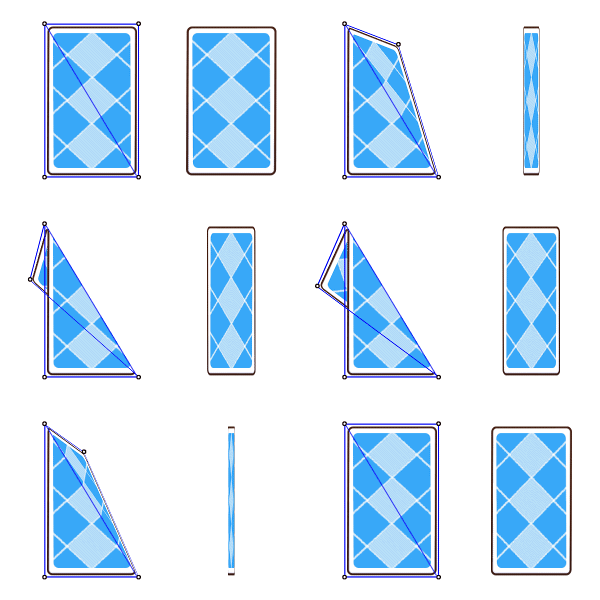 |
Turn on if you want the part to disappear when the polygon is flipped over.
Turn off if you want to create a part flipped horizontally with the polygon flipped over.
How to Calculate Triangulation
The triangulation calculation method has been changed since Cubism 3.0.07.
Automatic Polygon => Triangle Transformation (Automatic Edge Connection)
Both Cubism 2.1 and 3.0 or later have a mechanism to convert a polygon (square or larger) or unconnected points into a triangle by connecting them.
This allows us to draw at high speed using 3D hardware.
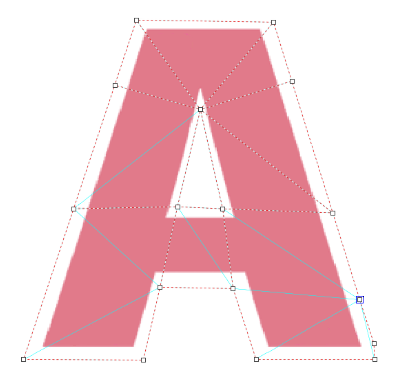
The light blue area in the figure is an auto connection
Cubism 2.1 calculation method:
2.1 uses a very simple method of connection, whereby squares and other objects are triangulated without consideration of angles.
The calculations were such that the connection was made in a shape that exceeded a pentagon and was not very appropriate.
Cubism 3.0 or later calculation method:
3.0 or later, the structure has been changed to generate triangles as naturally as possible, even for polygons beyond the pentagon and in situations where the points are not well connected.
Note: The system was buggy until 3.0.06, but has become significantly more stable since 3.0.07.
For models generated from 2.1 cmox
Before 3.0.06:
- When loading the .cmox file created in 2.1, the process of creating triangles was being executed using the calculation method for 3.0.
(However, due to differences in calculation methods between 2.1 and 3.0 and a bug up to 3.0.06, some meshes loaded from 2.1 were missing.)
3.0.07 or later:
- To ensure that models created in 2.1 can be safely used in the SDK for 3.0 without modification, the .cmox file is now triangulated in Cubism 3.0 using the same calculation method as in 2.1 when loaded.
- In 3.0, the calculation method for 2.1 works as long as no mesh editing (automatic or manual) is performed on each ArtMesh. The calculation method has been changed so that MOC3 and MOC files can be safely used with the same results as 2.1 if exported as they are.
- The system is designed to switch to the 3.0 off-style triangulation process once the mesh editing (automatic or manual) of each ArtMesh is performed in the 3.0.
- 3.0.07 fixes a bug that occurred prior to 3.0.06 and improves the connection to be cleaner and safer.
