About the View Area
Updated: 04/15/2025
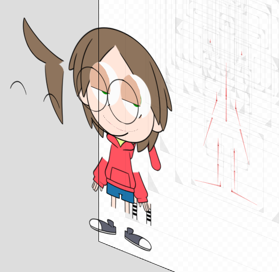
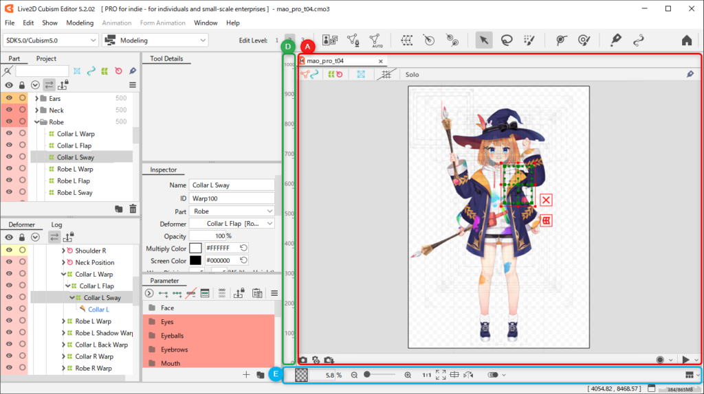
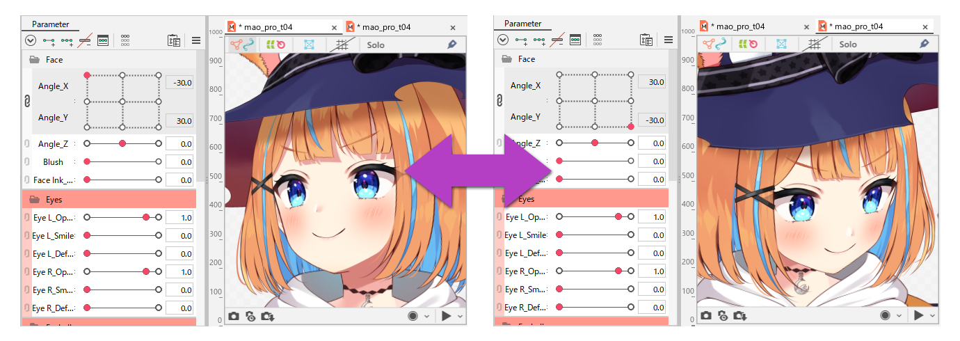
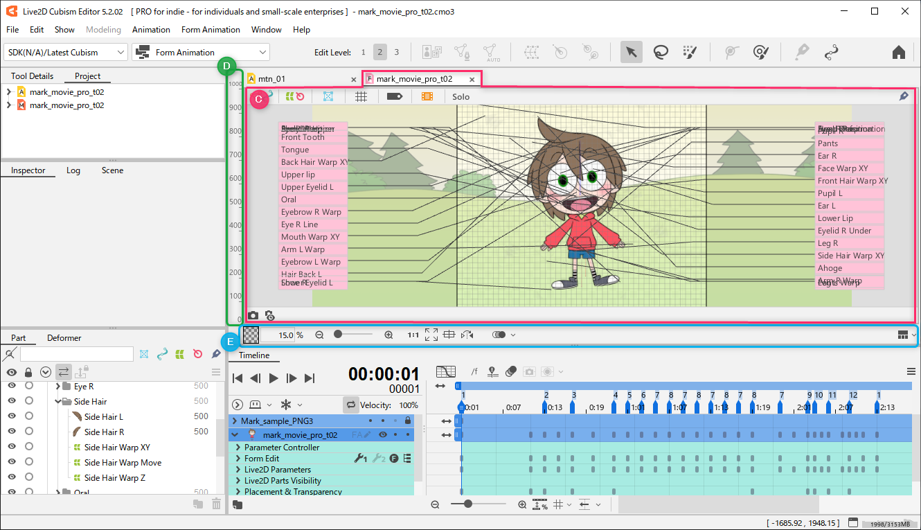
The View area is the area where the Live2D model is displayed.
Used to select and place ArtMesh on the canvas and to move meshes and deformers.
About views
Views can be broadly classified into the following types.
Modeling View
Used to transform objects and create keyforms.
Editing ArtMeshes and creating parameters are also done in this View.
Animation View
Used to create scenes and keyframe motion on the timeline.
Load a model file and create an animation by moving the parameters you set.
Form Animation (FA) View
Used to create form animations.
Form Animation is the function to edit a shape (form) directly on the animation editing timeline without affecting the model data.
The Cubism Editor has an appropriate workspace for each View.
For more information on workspaces, please see “Workspace.”
View Area Functions
This section describes each function within the View area.
A. Modeling View
Please refer to the respective explanations for D/E at the bottom of this page.
| Number | Details |
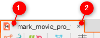
| (1) |
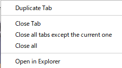
[About tabs]
|
| (2) | Delete tabs: Click the [X] button at the right end of a tab to delete the currently selected tab. |
| Number | Details |
|---|---|
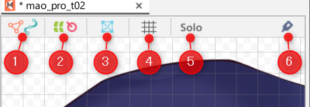
(1) | Lock drawable objects: Only meshes can be shown/hidden and locked on the View. Objects are displayed as they are. The target objects are [ArtMesh] and [ArtPath]. |
(2) | Lock deformers: Only deformers can be shown/hidden and locked on the View. |
(3) | Show/hide drawable objects: Drawable objects can be shown/hidden and locked on the View. The target objects are [ArtMesh] and [ArtPath]. |
| (4) | Show/hide grid: Grid can be switched between being shown or hidden. |
| (5) | Solo: Selected objects can be displayed by themselves. See “Solo Function” for more information. |
(6) | Switch glue on/off: The glue can be used to temporarily release or reconnect the glued (bound) state. For more information on glue, see “Glue.” |
| Number | Details |
|---|---|
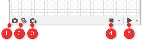
| (1) | Snapshot: Memorize the keyform image of the current value in semi-transparent form. One snapshot can be saved. See “Snapshot Function” for more information. |
| (2) | Show/hide snapshots: Shows/hides stored snapshots. |
| (3) | Save snapshots: Save the snapshot as an image in the Parts palette. |
| (4) | Record button: Clicking the Record button displays “Recording…” in the lower-right corner in the View, and the parameters you move during recording are saved as keyframes. (Motion during random pose playback can also be saved as keyframes.) For more information, see “Record Parameter Operations and Generate Animations.” Recording Settings: Click the ∨ button to open the Recording Settings dialog box. You can select where to add scenes generated by the recording function. 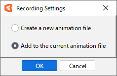 • Generate new animation data Create new animation data (CAN3). • Add to current animation data Add a scene to the animation data (CAN3) currently associated with it. |
| (5) | Random pose: Click the Start button to move multiple parameters randomly. See “Random Pose” for more information. Random Pose menu: 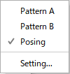 Click the ∨ button to select a pattern to move randomly. The parameter you want to move can also be selected from [Setting]. The random pose can also be played back in the [Physics Settings] dialog box. |
B. Animation View
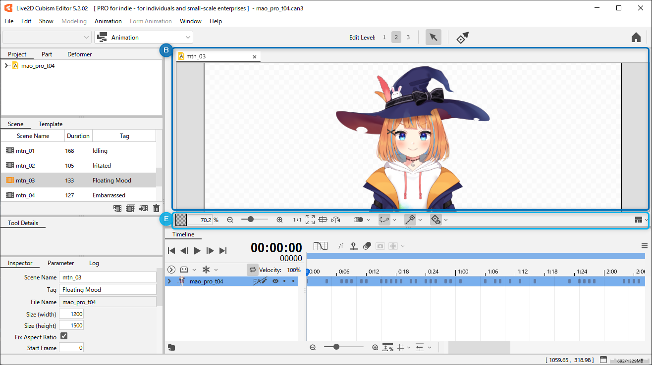
Please refer to the explanation at the bottom of the page for more information on E.
| Number | Details |
|---|---|
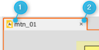
| (1) | Tab: “About Tabs” and “About Tab Menu” are the same as for the Modeling View. |
| (2) | Delete tabs: Click the [X] button at the right end of a tab to delete the currently selected tab. |
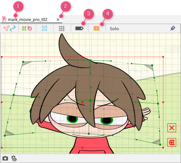
C. Form Animation (FA) View
Please refer to the respective explanations for D/Eat the bottom of this page.
| Number | Details |
|---|---|
| (1) | Tab: “About Tabs” and “About Tab Menu” are the same as for the Modeling View. |
| (2) | Delete tabs: Click the [X] button at the right end of a tab to delete the currently selected tab. |
| (3) | Label: Shows/hides labels of form-edited objects. |
(4) | Show/hide animation previews: Shows/hides the animation preview. See “Animation Preview” for more information. |
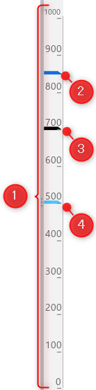
D. Draw order slider for drawable objects
| Number | Details |
|---|---|
| (1) | Draw order slider: When a drawable object or part is selected, a bar indicating the draw order is displayed on the draw order slider. The draw order can also be changed by dragging the bar. 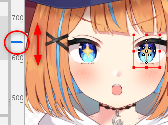 Right-clicking on the draw order slider brings up a menu from which you can enable/disable the bar operation [Lock Draw Order Slider]. |
| (2) | When a drawable object is selected, the bar is displayed in blue. |
| (3) | When a part is selected, the bar is displayed in black (white in the dark theme). |
| (4) | When a draw order group is selected, the bar is displayed in light blue. |
See “About Draw Order” for information on how to set the draw order for drawable objects.
E. View control
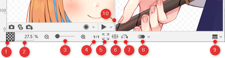
| Number | Details |
|---|---|
| (1) | Change background color: You can change or adjust the background color and opacity of the canvas in the View. |
(2) | Numerical control of display magnification: The size can be specified by entering a numerical value or by dragging left or right. |
| (3) | Expansion and contraction slider: The drawing magnification can be adjusted from “2” to “3200”%. Clicking the [-] and [+] icons on either side of the screen allows you to zoom in and out in steps. |
| (4) | Display in full scale: The image can be displayed in its original size at the time of PSD import. |
| (5) | Display all: The entire canvas can be displayed. |
| (6) | Focus display: The selected object appears in the center of the View. |
| (7) | Canvas inversion: Flip the canvas left or right. |
| (8) | Onion skin: Shows/hides the onion skin. For more information on onion skin, see “Onion Skin.” |
| (9) | Multiview settings: You can select the layout for split views. See “Multiview” for more information. |
(10)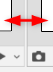 | Divider: Drag this area to change the screen size. |
Basic Operation of View Area
Operation |
Details | ||||
| Mouse wheel scroll | The canvas expands and contracts. | ||||
| [Space] + [drag] | The canvas can be moved. | ||||
| [Space] + [Shift] + [drag] | The canvas can be moved in a direction that is parallel to the direction in which the canvas was first moved. | ||||
| [Ctrl] + [Space] + [drag] | The canvas can be scaled up or down by 1%. | ||||
| [R] | The canvas can be flipped left or right. | ||||
| [R] + [drag] | The canvas can be rotated. | ||||
| [R] + [Shift] + [drag] | The canvas can be rotated in a grid. | ||||
| [R] + [double-click] | The canvas rotation can be reset. | ||||
| [Ctrl] + [0] | The entire view can be displayed. Use this to reset a canvas that has been scaled or rotated. |
||||
| Object selection | Click on an object to select it. [Shift] + [click] to select multiple objects. 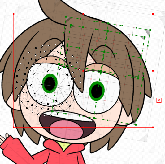 The tooltip of the object name displayed at the cursor position can be shown or hidden from the [Show] menu -> [Display name of object at cursor position]. |
||||
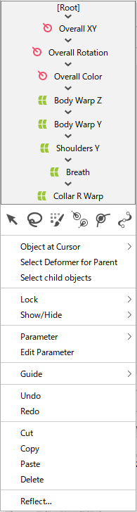
| [Right-click] on the target object |
Open the context menu.
At the top of the menu, the parent-child hierarchy of the deformer is displayed in a tree for selection. You can also hide it by going to “Environment settings” -> [View area] and clearing the [Show parent-child hierarchy of deformers] check box. |
||||
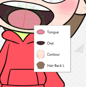
| On the target art mesh, [Ctrl] + [right click]. |
Displays the ArtMesh pop-up list.
|
||||
| After selecting ArtMesh deformer [Delete] key |
Deletes the selected ArtMesh deformer. | ||||
|
[E] key + [drag] to display the canvas in 3D [W] key + [drag] to display draw order in 3D [E] key / [W] key + [double click] to reset each 3D display |
The [E] key + [drag] displays the canvas in 3D, and the [W] key + [drag] displays the draw order in 3D, allowing the user to visually check the overall draw order. This mode can be restored by changing the mode to [Display All].
Precautions |
||||
| Click [Show] menu -> [Hide selection state] |
When an object is selected on the canvas, the UIs (ArtMesh vertices, mesh lines, and deformer border lines) are hidden.
Shortcuts can also be set. |