蒙版前处理方法(Native)
最終更新: 2023年2月21日
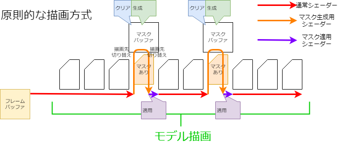
在Live2D Cubism SDK for Native中,为了保持智能手机等的绘制速度,在模型绘制处理开始时,采用了为一个蒙版缓冲区绘制所有蒙版形状的“预处理方法”。
在原理绘制方法中,每次绘制需要蒙版的Drawable时,都会绘制蒙版形状(见图)。
使用这种方法,每次Drawable需要蒙版时,都会发生切换渲染目标和清除缓冲区等相对高成本的处理。
因此,它可能会导致智能手机等上的绘图速度降低。
但是,仅仅提前准备好蒙版需要多个蒙版缓冲区,这会给内存记忆带来压力。
为了解决这个问题,可以对一个蒙版缓冲区进行以下处理,在将其视为正在使用多个蒙版缓冲区的同时,减少内存记忆压力。
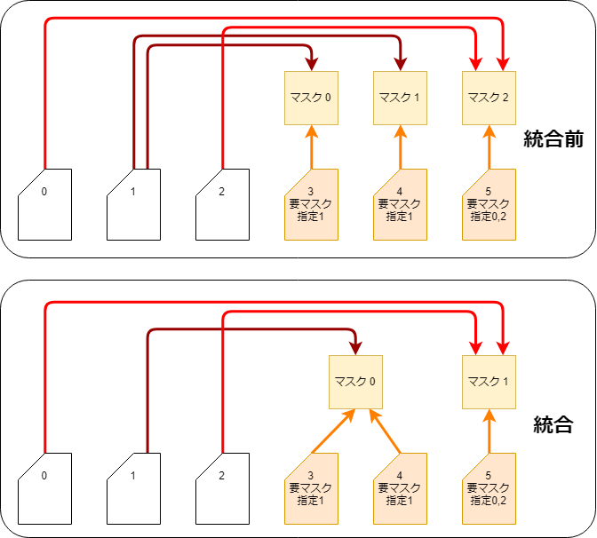
蒙版集成
由于所有的蒙版都是预先生成的,因此接受相同蒙版指定的Drawable可以通过使用相同蒙版图片以减少生成的张数。
这个处理在CubismRenderer_OpenGLES2::Initialize函数调用中通过CubismClippingManager_OpenGLES2::Initialize函数完成。
void CubismClippingManager_OpenGLES2::Initialize(CubismModel& model, csmInt32 drawableCount, const csmInt32** drawableMasks, const csmInt32* drawableMaskCounts)
{
    // 注册所有使用剪贴蒙版的绘制物件
    // 剪贴蒙版通常仅限于几个
    for (csmInt32 i = 0; i < drawableCount; i++)
    {
        if (drawableMaskCounts[i] <= 0)
        {
            // 没有使用剪贴蒙版的图形网格(大多数情况下不使用)
            _clippingContextListForDraw.PushBack(NULL);
            continue;
        }

        // 检查是否与已有的ClipContext相同
        CubismClippingContext* cc = FindSameClip(drawableMasks[i], drawableMaskCounts[i]);
        if (cc == NULL)
        {
            // 如果不存在相同的蒙版则生成
            cc = CSM_NEW CubismClippingContext(this, drawableMasks[i], drawableMaskCounts[i]);
            _clippingContextListForMask.PushBack(cc);
        }

        cc->AddClippedDrawable(i);

        _clippingContextListForDraw.PushBack(cc);
    }
}
使用多个蒙版纹理
Cubism SDK for Native R6或更高版本中,您可以任意使用多个蒙版纹理。
因此,即使给模型设置了超过R5之前存在的36个蒙版上限的蒙版,也能够在SDK上正常显示。
但是,如果使用两个或多个蒙版纹理,则可以为一个蒙版纹理生成的蒙版上限数量为32个。
(仅使用一个蒙版时的蒙版上限数量为36个。相关详情会在之后说明。)
如果使用两个蒙版纹理,则可以使用的蒙版上限数量为32 * 2 = 64个。
使用多个蒙版纹理的设置如下。
int maskBufferCount = 2;

CubismRenderer renderer = Rendering::CubismRenderer::Create();
renderer->Initialize(cubismModel, maskBufferCount);
如果没有传递给CubismRenderer::Initialize()的第二参数,则只会生成并使用一个蒙版纹理。
renderer->Initialize(cubismModel);
按颜色信息分开
蒙版缓冲区是一个RGBA视频数组,与通常的纹理缓冲区等一样。
通常的蒙版处理仅使用此A通道来应用蒙版,而不使用RGB通道。
因此,通过在RGBA中具有单独的蒙版数据,一个蒙版缓冲区可以作为四个蒙版缓冲区处理。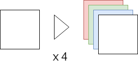
分割分开
当4张蒙版图片不够用时,通过2等份、4等份和9等份处理蒙版缓冲区来增加蒙版数量。
由于还存在按颜色信息分割的情况,因此最多可以保存4 × 9、共36个不同蒙版。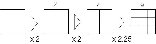
此外,为防止蒙版图片被压扁,请使用应用蒙版的所有Drawable矩形绘制蒙版。
因此,需要生成范围、蒙版、使用蒙版生成矩阵。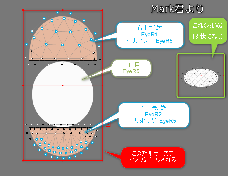
使用多个蒙版纹理时,分割方法与仅使用一个蒙版纹理时相同。
但是,当使用多个蒙版纹理时,每个蒙版纹理的蒙版分配会尽可能平均分配,因此即使使用相同的模型也可以提高绘制质量。(如果增加蒙版纹理,处理成本会相应增加。)
例如,拥有32个蒙版的模型通常使用一个蒙版纹理绘制32个蒙版,但使用2个蒙版纹理时的蒙版分配为“每个16个”。
检查矩形
在蒙版生成的第一步中,对于每个蒙版,检查完全覆盖蒙版的矩形。
void CubismClippingManager_OpenGLES2::CalcClippedDrawTotalBounds(CubismModel& model, CubismClippingContext* clippingContext)
{
    // 被剪贴蒙版(要添加蒙版的绘制物件)的全体矩形
    csmFloat32 clippedDrawTotalMinX = FLT_MAX, clippedDrawTotalMinY = FLT_MAX;
    csmFloat32 clippedDrawTotalMaxX = FLT_MIN, clippedDrawTotalMaxY = FLT_MIN;

    // 判断该蒙版是否真的需要
    // 如果至少可以使用一个使用该剪贴的“绘制物件”,则需要生成蒙版

    const csmInt32 clippedDrawCount = clippingContext->_clippedDrawableIndexList->GetSize();
    for (csmInt32 clippedDrawableIndex = 0; clippedDrawableIndex < clippedDrawCount; clippedDrawableIndex++)
    {
        // 查找使用蒙版的绘制物件的绘制矩形
        const csmInt32 drawableIndex = (*clippingContext->_clippedDrawableIndexList)[clippedDrawableIndex];

        const csmInt32 drawableVertexCount = model.GetDrawableVertexCount(drawableIndex);
        csmFloat32* drawableVertexes = const_cast<csmFloat32*>(model.GetDrawableVertices(drawableIndex));

        csmFloat32 minX = FLT_MAX, minY = FLT_MAX;
        csmFloat32 maxX = FLT_MIN, maxY = FLT_MIN;

        csmInt32 loop = drawableVertexCount * Constant::VertexStep;
        for (csmInt32 pi = Constant::VertexOffset; pi < loop; pi += Constant::VertexStep)
        {
            csmFloat32 x = drawableVertexes[pi];
            csmFloat32 y = drawableVertexes[pi + 1];
            if (x < minX) minX = x;
            if (x > maxX) maxX = x;
            if (y < minY) minY = y;
            if (y > maxY) maxY = y;
        }

        //
        if (minX == FLT_MAX) continue; // 由于无法获得任何有效点,因此跳过

        // 应用到全体矩形
        if (minX < clippedDrawTotalMinX) clippedDrawTotalMinX = minX;
        if (minY < clippedDrawTotalMinY) clippedDrawTotalMinY = minY;
        if (maxX > clippedDrawTotalMaxX) clippedDrawTotalMaxX = maxX;
        if (maxY > clippedDrawTotalMaxY) clippedDrawTotalMaxY = maxY;
    }
    if (clippedDrawTotalMinX == FLT_MAX)
    {
        clippingContext->_allClippedDrawRect->X = 0.0f;
        clippingContext->_allClippedDrawRect->Y = 0.0f;
        clippingContext->_allClippedDrawRect->Width = 0.0f;
        clippingContext->_allClippedDrawRect->Height = 0.0f;
        clippingContext->_isUsing = false;
    }
    else
    {
        clippingContext->_isUsing = true;
        csmFloat32 w = clippedDrawTotalMaxX - clippedDrawTotalMinX;
        csmFloat32 h = clippedDrawTotalMaxY - clippedDrawTotalMinY;
        clippingContext->_allClippedDrawRect->X = clippedDrawTotalMinX;
        clippingContext->_allClippedDrawRect->Y = clippedDrawTotalMinY;
        clippingContext->_allClippedDrawRect->Width = w;
        clippingContext->_allClippedDrawRect->Height = h;
    }
}
颜色分开、分割分开的编排决定
确定每个蒙版所属的蒙版缓冲区的颜色通道和分割位置。
void CubismClippingManager_OpenGLES2::SetupLayoutBounds(csmInt32 usingClipCount) const
{
    // 尽可能使用一个RenderTexture来编排蒙版
    // 如果蒙版组数为4个或更少,则为RGBA各通道置入一个蒙版,如果为5以上、6个以下,则将RGBA置入为2,2,1,1

    // 按顺序使用RGBA。
    const csmInt32 div = usingClipCount / ColorChannelCount; // 一个通道中要置入的基本蒙版数
    const csmInt32 mod = usingClipCount % ColorChannelCount; // 剩余,逐一分配到该编号的通道

    // 准备RGBA各通道(0:R, 1:G, 2:B, 3:A)
    csmInt32 curClipIndex = 0; // 按顺序设置

    for (csmInt32 channelNo = 0; channelNo < ColorChannelCount; channelNo++)
    {
        // 在该通道上编排的数量
        const csmInt32 layoutCount = div + (channelNo < mod ? 1 : 0);

        // 决定如何分割
        if (layoutCount == 0)
        {
            // 什么都不做
        }
        else if (layoutCount == 1)
        {
            // 直接使用所有内容
            CubismClippingContext* cc = _clippingContextListForMask[curClipIndex++];
            cc->_layoutChannelNo = channelNo;
            cc->_layoutBounds->X = 0.0f;
            cc->_layoutBounds->Y = 0.0f;
            cc->_layoutBounds->Width = 1.0f;
            cc->_layoutBounds->Height = 1.0f;
        }
        else if (layoutCount == 2)
        {
            for (csmInt32 i = 0; i < layoutCount; i++)
            {
                csmInt32 xpos = i % 2;

                CubismClippingContext* cc = _clippingContextListForMask[curClipIndex++];
                cc->_layoutChannelNo = channelNo;

                cc->_layoutBounds->X = xpos * 0.5f;
                cc->_layoutBounds->Y = 0.0f;
                cc->_layoutBounds->Width = 0.5f;
                cc->_layoutBounds->Height = 1.0f;
                // 2等份并使用UV
            }
        }
        else if (layoutCount <= 4)
        {
            // 4等份并使用
            for (csmInt32 i = 0; i < layoutCount; i++)
            {
                csmInt32 xpos = i % 2;
                csmInt32 ypos = i / 2;

                CubismClippingContext* cc = _clippingContextListForMask[curClipIndex++];
                cc->_layoutChannelNo = channelNo;

                cc->_layoutBounds->X = xpos * 0.5f;
                cc->_layoutBounds->Y = ypos * 0.5f;
                cc->_layoutBounds->Width = 0.5f;
                cc->_layoutBounds->Height = 0.5f;
            }
        }
        else if (layoutCount <= 9)
        {
            // 9等份并使用
            for (csmInt32 i = 0; i < layoutCount; i++)
            {
                csmInt32 xpos = i % 3;
                csmInt32 ypos = i / 3;

                CubismClippingContext* cc = _clippingContextListForMask[curClipIndex++];
                cc->_layoutChannelNo = channelNo;

                cc->_layoutBounds->X = xpos / 3.0f;
                cc->_layoutBounds->Y = ypos / 3.0f;
                cc->_layoutBounds->Width = 1.0f / 3.0f;
                cc->_layoutBounds->Height = 1.0f / 3.0f;
            }
        }
        else
        {
            CubismLogError("not supported mask count : %d", layoutCount);
        }
    }
}
蒙版绘制,使用蒙版生成矩阵
根据绘制前检查的矩形范围及其所属位置,准备用于蒙版生成和蒙版使用的转变矩阵。
           // --- 实际绘制一个蒙版 ---
            CubismClippingContext* clipContext = _clippingContextListForMask[clipIndex];
            csmRectF* allClippedDrawRect = clipContext->_allClippedDrawRect; // 使用该蒙版的所有绘制物件逻辑座标上的矩形边界
            csmRectF* layoutBoundsOnTex01 = clipContext->_layoutBounds; // 将蒙版放入其中

            // 对模型座标上的矩形添加适当的余量并使用
            csmFloat32 MARGIN = 0.05f;
            _tmpBoundsOnModel.SetRect(allClippedDrawRect);
            _tmpBoundsOnModel.Expand(allClippedDrawRect->Width * MARGIN, allClippedDrawRect->Height * MARGIN);
            // ########## 本来,不使用全体分配区域的情况下,所需最小尺寸为宜

            // 求用于着色器的公式。不考虑旋转时,如下所示
            // movePeriod' = movePeriod * scaleX + offX		  [[ movePeriod' = (movePeriod - tmpBoundsOnModel.movePeriod)*scale + layoutBoundsOnTex01.movePeriod ]]
            csmFloat32 scaleX = layoutBoundsOnTex01->Width / _tmpBoundsOnModel.Width;
            csmFloat32 scaleY = layoutBoundsOnTex01->Height / _tmpBoundsOnModel.Height;

            // 找到生成蒙版时要使用的矩阵
            {
                // 求传递给着色器的矩阵 <<<<<<<<<<<<<<<<<<<<<<<< 需要优化(逆序计算可以很简单)
                _tmpMatrix.LoadIdentity();
                {
                    // 将Layout0 .. 1转变为−1 .. 1
                    _tmpMatrix.TranslateRelative(-1.0f, -1.0f);
                    _tmpMatrix.ScaleRelative(2.0f, 2.0f);
                }
                {
                    // view to Layout0..1
                    _tmpMatrix.TranslateRelative(layoutBoundsOnTex01->X, layoutBoundsOnTex01->Y); //new = [translate]
                    _tmpMatrix.ScaleRelative(scaleX, scaleY); //new = [translate][scale]
                    _tmpMatrix.TranslateRelative(-_tmpBoundsOnModel.X, -_tmpBoundsOnModel.Y);
                    //new = [translate][scale][translate]
                }
                // tmpMatrixForMask为计算结果
                _tmpMatrixForMask.SetMatrix(_tmpMatrix.GetArray());
            }

            // --------- 计算draw时的mask参考矩阵
            {
                // 求传递给着色器的矩阵 <<<<<<<<<<<<<<<<<<<<<<<< 需要优化(逆序计算可以很简单)
                _tmpMatrix.LoadIdentity();
                {
                    _tmpMatrix.TranslateRelative(layoutBoundsOnTex01->X, layoutBoundsOnTex01->Y); //new = [translate]
                    _tmpMatrix.ScaleRelative(scaleX, scaleY); //new = [translate][scale]
                    _tmpMatrix.TranslateRelative(-_tmpBoundsOnModel.X, -_tmpBoundsOnModel.Y);
                    //new = [translate][scale][translate]
                }

                _tmpMatrixForDraw.SetMatrix(_tmpMatrix.GetArray());
            }

            clipContext->_matrixForMask.SetMatrix(_tmpMatrixForMask.GetArray());

            clipContext->_matrixForDraw.SetMatrix(_tmpMatrixForDraw.GetArray());
蒙版缓冲区的动态大小变更
GLES2渲染器提供了一个API,以在运行时变更蒙版缓冲区的大小。
目前,蒙版缓冲区的大小设置为256 * 256(像素)作为初始值,但如果要将蒙版生成区域切割成9张,则将在85 * 85(像素)的矩形区域内绘制的蒙版形状进一步放大,作为剪贴区域使用。
因此,剪贴结果的边缘会模糊或渗色。
作为解决方案,我们提供了一个 API,可以在程序执行时变更蒙版缓冲区的大小。
例如,通过将蒙版缓冲区的大小从256 * 256变更为1024 *1024,如果将蒙版生成区域切成9张,则可以在341*341的矩形区域中绘制蒙版形状,因此,您还可以放大并将其用作剪贴区域,以消除剪贴结果边缘的模糊和渗色。
* 扩大蒙版缓冲区的大小 ⇒ 如果要处理的像素增加,速度会变慢,但绘制结果会很漂亮。
* 缩小蒙版缓冲区的大小 ⇒ 由于要处理的像素减少了,所以速度会更快,但是绘制结果会很脏。
void CubismRenderer_OpenGLES2::SetClippingMaskBufferSize(csmInt32 size)
{
    // 放弃/重新创建副本以变更FrameBuffer的大小
    CSM_DELETE_SELF(CubismClippingManager_OpenGLES2, _clippingManager);

    _clippingManager = CSM_NEW CubismClippingManager_OpenGLES2();

    _clippingManager->SetClippingMaskBufferSize(size);

    _clippingManager->Initialize(
        *GetModel(),
        GetModel()->GetDrawableCount(),
        GetModel()->GetDrawableMasks(),
        GetModel()->GetDrawableMaskCounts()
    );
}
预处理方法能提高性能的原因
作为移动终端特有的情况,GPU的Clear指令和渲染目标切换指令的处理成本可能高于其他指令。
在使用原理方法绘制时,会根据需要蒙版的Drawable数量执行这些处理成本较高的指令。
然而,在预处理方法的情况下,可以减少这些指令的执行次数,这有望提高在智能手机等上的性能。
为了实际理解效果,我们来衡量一下每个处理单元在渲染中的时间成本。
作为测量方法,请检查下面显示的源代码。 按构建单独测量层。
另外,测试对象的模型是Haru集成的。
准备有两种Android设备和一种Windows设备进行测量。
测量是通过Android端的clock_gettime函数和Windows端的QueryPerformanceCounter函数,将结果缓存到缓冲区并计算平均值。
剪贴蒙版生成器(层1)
void CubismClippingManager_OpenGLES2::SetupClippingContext(CubismModel& model, CubismRenderer_OpenGLES2* renderer)
{
  ・
  ・
  ・
        {	// ★绘制目标切换测量
            P_TIME1(ProcessingTime cl(s_switch);)
            // ---------- 蒙版绘制处理-----------
            // 将蒙版的RenderTexture设置为active
            glBindFramebuffer(GL_FRAMEBUFFER, _maskRenderTexture);
        }

        {	// ★缓冲区清空(填充处理)测量
            P_TIME1(ProcessingTime cl(s_clear);)
            // 清除蒙版
            // (暂定规格)1为无效(未绘制)区域,0为有效(绘制)区域。(在着色器中使用Cd * Cs乘以接近0的值以制作蒙版。当乘以1时没有任何反应)
            glClearColor(1.0f, 1.0f, 1.0f, 1.0f);
            glClear(GL_COLOR_BUFFER_BIT);
        }
 ・
 ・
 ・
        {	// ★绘制目标切换测量2
            P_TIME1(ProcessingTime cl(s_switch);)
            // --- 后处理 ---
            glBindFramebuffer(GL_FRAMEBUFFER, oldFBO); // 返回绘制对象
        }
  ・
  ・
  ・
}
CubismClippingManager_OpenGLES2::SetupClippingContext测量切换绘制目标和填充的时间。
全体模型绘制(混合层1、2)
void CubismRenderer_OpenGLES2::DoDrawModel()
{


    {	// ★测量全体蒙版缓冲区的生成
        P_TIME2(ProcessingTime makemask(s_maskmake);)
        if (_clippingManager != NULL)
        {
            PreDraw();
            _clippingManager->SetupClippingContext(*GetModel(), this);
        }
    }

    { // ★测量绘制预处理
        P_TIME1(ProcessingTime makemask(s_predraw);)
        // 即使在上述剪贴处理中,也将调用一次PreDraw,敬请注意!!
        PreDraw();
    }


    const csmInt32 drawableCount = GetModel()->GetDrawableCount();
    const csmInt32* renderOrder = GetModel()->GetDrawableRenderOrders();


    { // ★测量排序时间
        P_TIME1(ProcessingTime makemask(s_sort);)
        // 按绘制顺序排序索引
        for (csmInt32 i = 0; i < drawableCount; ++i)
        {
            const csmInt32 order = renderOrder[i];
            _sortedDrawableIndexList[order] = i;
        }
    }

    { // ★测量除蒙版以外的绘制时间
        P_TIME2(ProcessingTime makemask(s_draw);)
        // 绘制
        for (csmInt32 i = 0; i < drawableCount; ++i)
        {
            const csmInt32 drawableIndex = _sortedDrawableIndexList[i];

            // 设置剪贴蒙版
            SetClippingContextBufferForDraw((_clippingManager != NULL)
                ? (*_clippingManager->GetClippingContextListForDraw())[drawableIndex]
                : NULL);

            IsCulling(GetModel()->GetDrawableCulling(drawableIndex) != 0);

            DrawMesh(
                GetModel()->GetDrawableTextureIndices(drawableIndex),
                GetModel()->GetDrawableVertexIndexCount(drawableIndex),
                GetModel()->GetDrawableVertexCount(drawableIndex),
                const_cast<csmUint16*>(GetModel()->GetDrawableVertexIndices(drawableIndex)),
                const_cast<csmFloat32*>(GetModel()->GetDrawableVertices(drawableIndex)),
                reinterpret_cast<csmFloat32*>(const_cast<Core::csmVector2*>(GetModel()->GetDrawableVertexUvs(drawableIndex))),
                GetModel()->GetDrawableOpacity(drawableIndex),
                GetModel()->GetDrawableBlendMode(drawableIndex)
            );
        }
    }

    { // ★测量绘制后处理
        P_TIME1(ProcessingTime makemask(s_post);)
        //
        PostDraw();
    }
}
测量绘制前、排序和绘制后处理。
通过划分层在蒙版生成和其他绘制的粗略中也进行测量。
绘制网格(第1层)
void CubismRenderer_OpenGLES2::DrawMesh(csmInt32 textureNo, csmInt32 indexCount, csmInt32 vertexCount
                                        , csmUint16* indexArray, csmFloat32* vertexArray, csmFloat32* uvArray
                                        , csmFloat32 opacity, CubismBlendMode colorBlendMode)
{
 ・
 ・
 ・
    { // ★测量着色器中的数据设置时间
        P_TIME1(ProcessingTime sharder(s_sharder);)
        CubismShader_OpenGLES2::GetInstance()->SetupShaderProgram(
            this, drawTextureId, vertexCount, vertexArray, uvArray
            , opacity, colorBlendMode, modelColorRGBA, IsPremultipliedAlpha()
            , GetMvpMatrix()
        );
    }

    { // ★测量单个绘制命令的时间
        P_TIME1(ProcessingTime gldraw(s_gldraw);)
        // 绘制多边形网格
        glDrawElements(GL_TRIANGLES, indexCount, GL_UNSIGNED_SHORT, indexArray);
    }

    // 后处理
    glUseProgram(0);
    SetClippingContextBufferForDraw(NULL);
    SetClippingContextBufferForMask(NULL);
}
在CubismRenderer_OpenGLES2::DrawMesh中,测量设置到着色器的时间和绘制命令的单次时间。
层3
void LAppModel::Update()
{
    {
        P_TIME3(ProcessingTime up(s_paramup);)
        const csmFloat32 deltaTimeSeconds = LAppPal::GetDeltaTime();
        _userTimeSeconds += deltaTimeSeconds;
      ・
      ・
      ・
        // 姿势设置
        if (_pose != NULL)
        {
            _pose->UpdateParameters(_model, deltaTimeSeconds);
        }
    }
    {
        P_TIME3(ProcessingTime ren(s_modelup);)

        _model->Update();

    }
}
void LAppModel::Draw(CubismMatrix44& matrix)
{
    P_TIME3(ProcessingTime ren(s_rendering);)

    matrix.MultiplyByMatrix(_modelMatrix);

    GetRenderer<Rendering::CubismRenderer_OpenGLES2>()->SetMvpMatrix(&matrix);

    DoDraw();
}
粗略将Update流程分为
参数计算、模型更新和渲染三个部分。
结果
| Android1 | Android2 | Winpc1 | |
| L1clear | 1781.20 | 218.80 | 26.80 |
| L1gldraw | 45.47 | 51.63 | 10.58 |
| L1sharder | 12.31 | 9.34 | 5.37 |
| L1post | 1.50 | 1.00 | 0.10 |
| L1switch | 10.70 | 56.30 | 7.80 |
| L1predraw | 15.90 | 8.20 | 2.20 |
| L1sort | 7.60 | 7.00 | 0.60 |
| L2MaskMake | 2686.80 | 1357.60 | 318.50 |
| L2draw | 4004.10 | 4013.20 | 1217.00 |
| L3paramupdate | 392.00 | 375.40 | 89.70 |
| L3modelupdate | 1357.50 | 1410.90 | 1070.40 |
| L3rendering | 6715.70 | 5233.70 | 1892.00 |
上表显示了上述部分的执行时间。
可以看到移动终端的Clear成本很高,切换渲染目标比其他指令重。
这条繁重的指令会在按原理方法绘制时,运行蒙版所需的Drawable。
由于该计算只能进行一次,因此有望提高在智能手机等上的性能。
将蒙版处理切换为高清方法
如上所述,每次绘制时生成蒙版的方法会影响低规格终端的性能。
但是,当画面质量比运行时的性能更重要时(例如最终输出为视频),此方法更适合。
在2018/12/20之后的SDK中,可以将蒙版处理切换为高清方式。
要切换到高清方法,请将true传递给以下API。
CubismRenderer::UseHighPrecisionMask()