Live2D Glossary
This page explains Live2D terms with images and descriptions.
A link to the relevant page on the manual website is provided below the text for a more detailed explanation.
A PDF file for printing is also available.
[Click here to download the PDF file for printing]
List of introductory terms
- Mesh / ArtMesh
- Polygon / Vertex / Edge
- Deformer (warp deformer, rotation deformer)
- Object
- Parameters
- Key / Keyform
- Part(s)
- Draw order
- Texture Atlas
Object Section
Mesh / ArtMesh
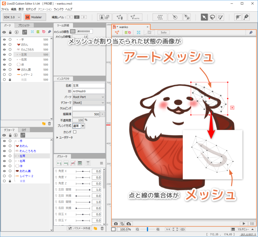
A set of triangles composed of vertices and lines is called a “mesh.”
PSD images loaded into Modeling View are always placed on the canvas with this “mesh” assigned.
An image with the mesh assigned is the “ArtMesh.”
Manual page: About ArtMesh
Polygon / Vertex / Edge
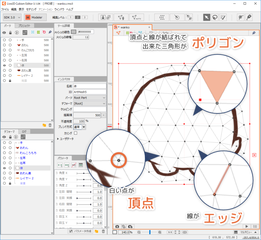
The triangles of a mesh, which is a set of triangles composed of vertices and lines, are called “polygons.”
The white points of a mesh are called “vertices.”
The lines of a mesh are called “edges.”
Deformer (warp deformer, rotation deformer)
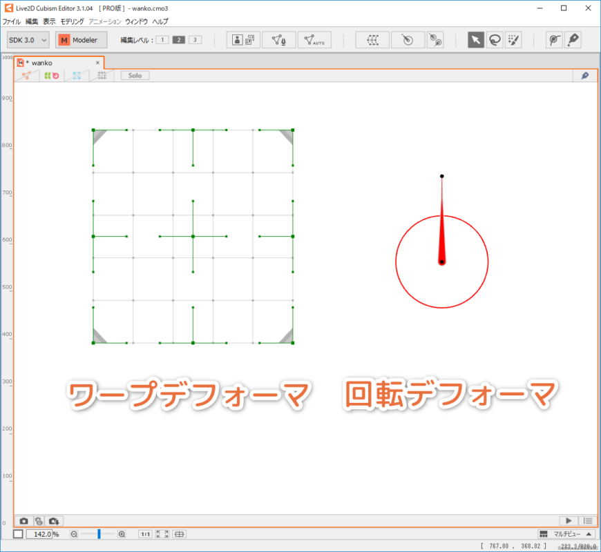
A container in which the vertices of an ArtMesh can be deformed and moved together is called a “deformer.”
There are two types of deformers: “Warp deformers,” which can create curved shapes, and “rotation deformers,” which can rotate and scale.
Each can do different things, so they are used for different purposes.
Manual page: About Deformer
Object
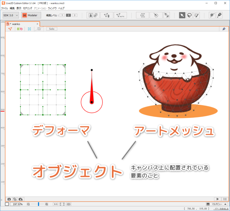
Each element placed on the canvas, such as an ArtMesh or deformer, is called an “object.”
Parameter Section
Parameters
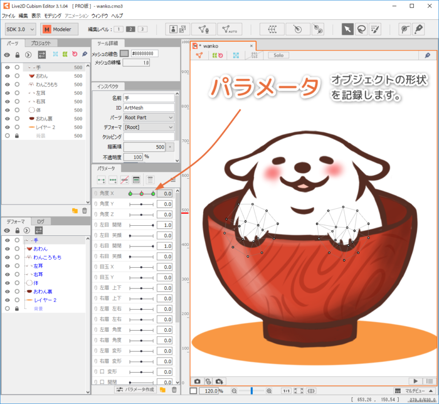
“Parameters” can be used to store the deformation, position, etc. of an object.
Manual page: About Parameters
Key / Keyform
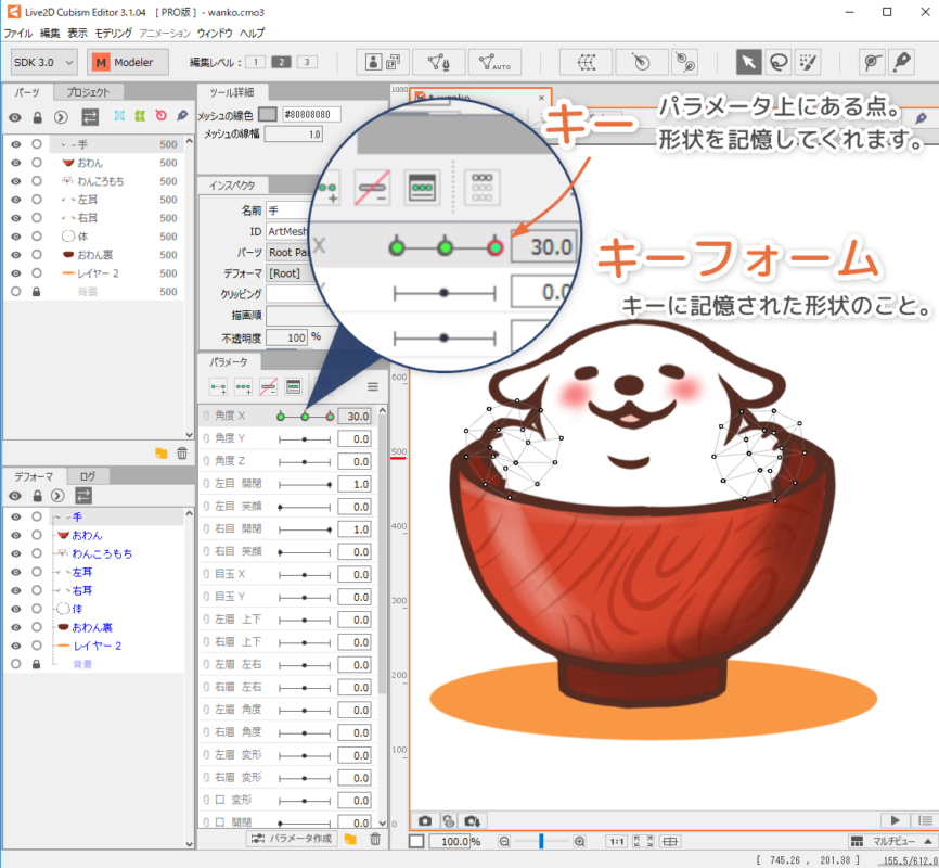
The point on the parameter where the shape is stored is called the “key.”
The shape specified by a key is called a “keyform.”
Manual page: Edit Parameters
Other
Part(s)
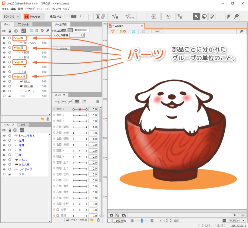
Groups of characters divided by their components (eyes, nose, etc.) are called “Parts.”
“Parts” are displayed in the Parts palette section.
Manual page: About Parts
Draw order
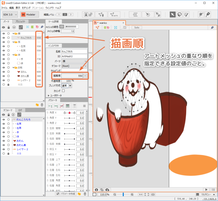
The value that specifies the order in which the ArtMeshes overlap is called the “draw order.”
It can be set between 0-1000. The larger the value, the more the ArtMesh will be displayed in front.
Manual page: About Draw Order
Texture Atlas
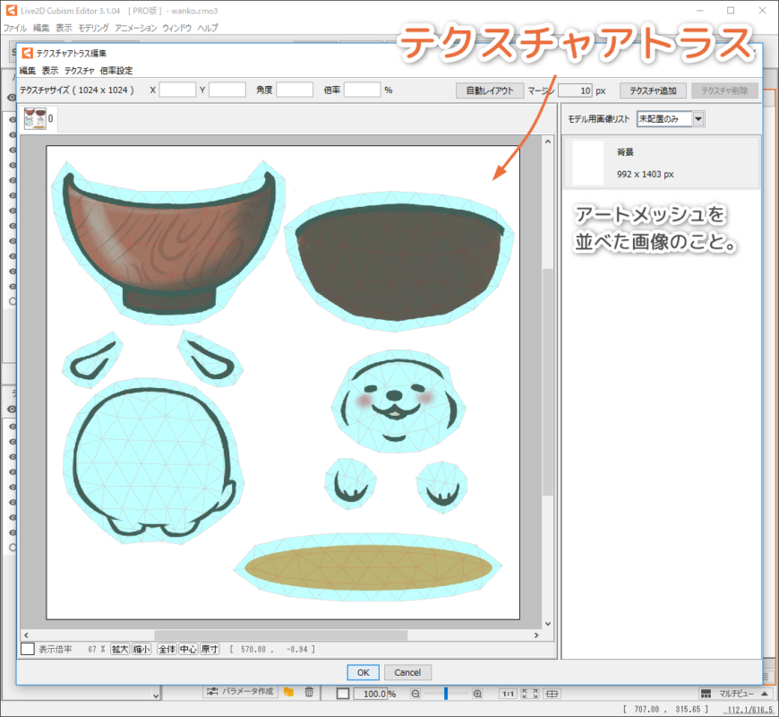
The image showing ArtMeshes side-by-side is called a “texture atlas.”
Typically, the format is PNG and the image size is created as n squares of 2.
This is required when exporting models for embedding in the SDK or for Cubism 2.1.
(Not required for video applications.)
Manual page: Edit Texture Atlas