Parameter palette
Updated: 02/13/2024
The Parameter palette manages “parameters” that tie the degree of deformation of an object to a numerical value.
This page explains the icons on the palette and basic operations.
For more information on the functions, see the respective pages in the parameter category.
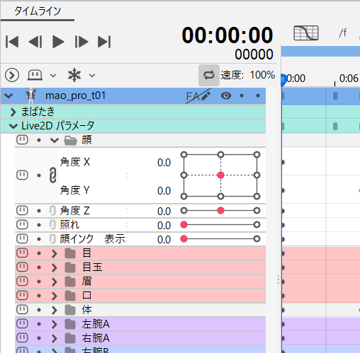
Parameter Palette

| Letter | Item |
|---|---|
| a | Buttons used for key editing |
| b | Other buttons |
| c | Parameter bar |
| d | Popup that appears when you click on a parameter slider |
| e | Buttons used to create new parameters and parameter groups and to delete them |
| f | Expand/collapse all the parameter group |
| g | Parameter group Note: Groups are created by putting parameters inside them. |
a. Buttons used for key editing
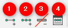
| Number | Item | Details |
|---|---|---|
| (1) | Add 2 keys | Clicking with any object and parameter selected automatically inserts keys into the minimum and maximum values of the parameter. |
| (2) | Add 3 keys | Clicking with any object and parameter selected automatically inserts keys into the minimum, intermediate, and maximum values of the parameter. |
| (3) | Delete all keys | Clicking with keyed objects and parameters selected will delete all keys. |
| (4) | Edit keys manually | With any object and parameter selected, click to open the [Edit Keyforms] dialog box, where you can create a key at any value you want. The same operation can be performed by double-clicking on the parameter name while the object is selected. |
b. Other buttons
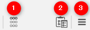
| Number | Item | Details |
| (1) | Refine Search |
Only the parameters for which the key of the currently selected object is set are narrowed down and displayed. |
| (2) |
Options for Paste Form Special |
Open the Options for the Paste Form Special dialog box. |
| (3) |
Palette Menu |
Reset to default values: Lock Default Forms: Parameter settings: Group settings: Motion-sync Settings: Settings for Eye Blinking and Lip-sync: Auto Generation of Facial Movement: Automatic Generation of Four Corner Forms: Motion Inversion: Multiple Keys Editing: Bulk Reflect: Extended Interpolation: Limit Settings for Blend Shape Weights: Synchronize parameter values across tabs: |
Tips
If you load a model (.cmox) with lip-sync settings in Cubism 2.1, the lip-sync checkbox must be checked in the “Settings for Eye Blinking and Lip-sync.”
c. Parameter bar

| Number | Item | Details |
| (1) | Link parameters below |
Click to link and display with the parameters immediately below. |
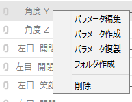
| (2) | Parameter name |
Display parameter names.
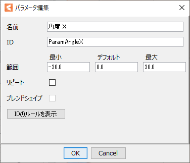
Edit Parameter:
Name: ID: Minimum, Default, Maximum: Repeat: Blend Shape: ID rule display: Create Parameter: Replicate parameters: Create folder: Delete: |
| (3) | Adjustment of parameter name display area |
You can adjust the display area by moving the [:], which is on the right of the parameter name, to the right or left.
|
| (4) | Parameter slider | The key value is displayed as a straight line from the minimum to the maximum value of the parameter. The key value is displayed as a straight line from the minimum to the maximum value of the parameter. |
| (5) | Parameter value | The current value is displayed. You can also specify a value by dragging it on the text box or typing it in directly. |
d. Popup that appears when you click on a parameter slider

| Number | Item | Details |
|---|---|---|
| (1) | Add Single Keyform | Create one key point with the current value. |
| (2) | Delete Keyform | Delete only the currently selected key. |
| (3) | Select / Reflect / Adjust / Change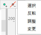 | The items on the left appear on mouse-over, allowing you to select the corresponding object and make various adjustments to the parameters. Parameter Adjustment |
e. Icons used to create new parameters and parameter groups, and delete them
| Number | Item | Details |
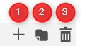
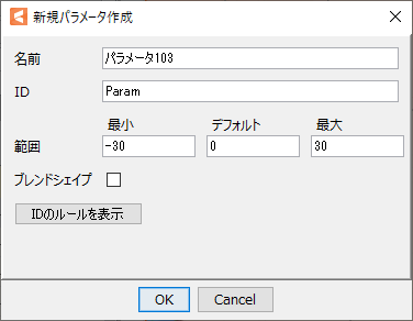
| (1) | Create Parameter |
Create a new parameter.
ID: Minimum, Default, Maximum: Blend Shape: ID rule display: |
| (2) | Create new folder | Create a new parameter group. Group names are created automatically, but can be changed by double-clicking on the name. By dragging the name part of a parameter and dropping it on a group, it can be stored in a group and organized for easy viewing (only one level can be created). |
| (3) | Delete | Click on a parameter or parameter group with it selected to delete the parameter. If a group is deleted with parameters in it, the parameters inside the group will be deleted. |
Tips
When a new parameter or parameter group is created, it is added under the currently selected parameter or parameter group.
If it is created with nothing selected, it will be placed at the bottom of the [Parameters] palette.
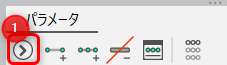
f. Expand/collapse all the parameter group
| Number | Item | Details |
|---|---|---|
| (1) | Expand/collapse all the parameter group | Expands/collapses all the parameter group. |
g. Parameter group
| Number | Item | Details |
|---|---|---|
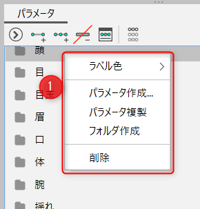
| (1) | Group name | The name of the group is displayed. By right-clicking on a group, the following functions will pop up. Label Color: You can set a color for a parameter group. See the “Color Coding of Parameter Groups” section of this page for details. Create Parameter: [Create New Parameter] dialog box opens. Replicate parameters: Duplicate parameter settings only. Objects and keyforms are not duplicated. Create folder: Create a new parameter group. Delete: You can delete groups. If a group is deleted with parameters in it, the parameters inside the group will be deleted. |
Basic Operation of the Parameter Palette
Add a key to the parameter:
See the “Add/Delete Keys to/from Parameters” page for details.
Select a parameter:
Clicking on a parameter name such as “Angle X” will change the color to gray and the parameter will be selected.
Change the order of parameters:
The order of parameters can be changed by dragging and dropping the “parameter name.”
Note: The same operation is used for parameter groups.
Note: Multiple selections can also be selected then dragged and dropped.
Set the current value:
Left-click on the slider or enter a value in the text box to the right of the parameter bar.
Select keys already created:
Right-click on the key’s area on the slider to select it for adhesion.
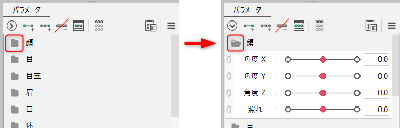
Expand/Collapse groups:
Click on the icon on the parameter group to expand or collapse it.
Parameter refine search
As the number of parameters increases, it becomes difficult to know which parameters are tied to an object or deformer.
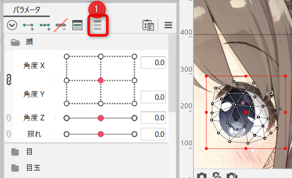
Clicking on the [Refine Search] button (1) in the Parameter palette will display only the parameters that are associated with the object, making it easier to find the parameter you want to adjust.
Multiple objects can be selected. Click again to return to the original view.

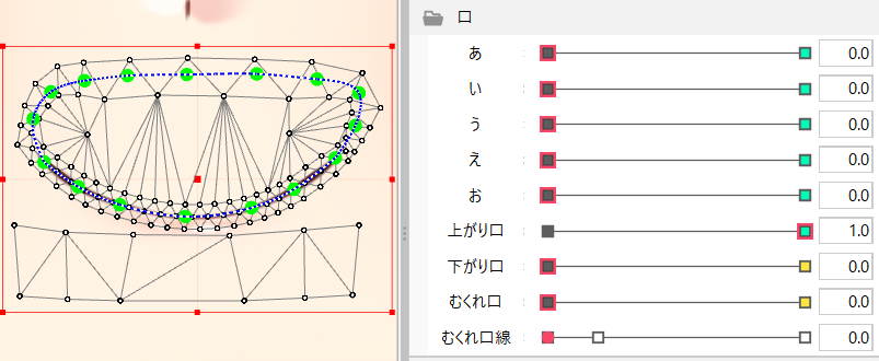
Display of Parameter Sliders
The parameter slider has two elements: “current value” and “key.”
The display changes depending on the presence or absence of keyforms and the state of object selection.
Current value:
 |
The current value with no keyform set. |
| The current value for which the keyform is set. | |
| The current value for which repeat is set. |
Key:
 |
This is the appearance when an object with the keyform set is not selected. |
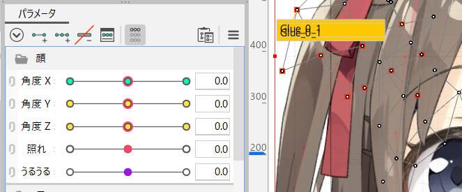
 |
This is the appearance when an object with a keyform set is selected. |
 |
This is the appearance when multiple objects with keyforms are selected and all the keyforms do not match. Note: For example, if you select the “right eyebrow” and “left ear” objects at the same time, the key for the parameter [BrowR deformation] will be displayed in yellow because the “left ear” is not related to the eyebrow movement. |
Blend Shape Parameters
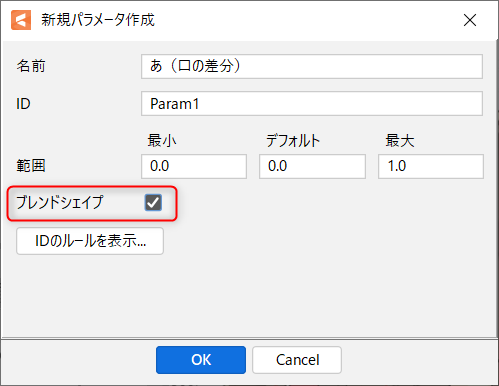
You can create Blend Shape parameters by checking the [Blend Shape] checkbox in the [Create New Parameter] dialog box.
It is recommended that the Blend Shape parameters be set to a minimum value of “0,” a default value of “0,” and a maximum value of “1.”
See “Blend Shape” for details.
The keys of the Blend Shape parameters are indicated by square marks.
The color change is the same as for normal keys.
Base key:
 |
This is the appearance when the keyform is not set. |
 |
This is the appearance when an object with a keyform set is selected. |
Blend shape key:
 |
This is the appearance when an object with the keyform set is not selected. |
 |
This is the appearance when an object with a keyform set is selected. |
 |
This is the appearance when multiple objects with keyforms are selected and all the keyforms do not match. |
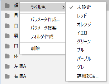
Color Coding of Parameter Groups
Parameter groups can be color-coded for easier viewing.
You can set a color for a parameter group by right-clicking the parameter group and selecting [Label Color].
If you wish to use a color other than those listed, go to [Advanced Settings] and select the color of your choice in the [Label Color Settings] dialog box.
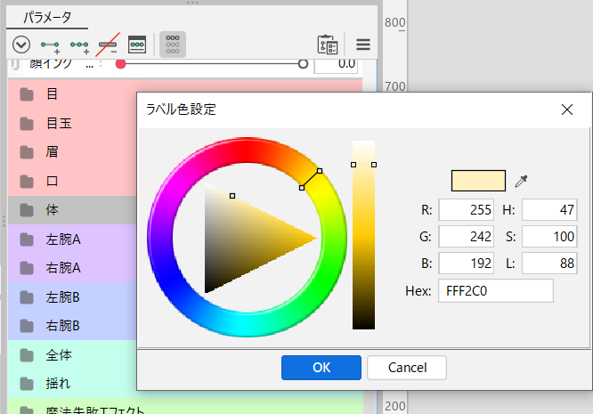
The colors you set will also be reflected on the timeline of the Animation View.